pooboo exercise bike manual

Pooboo Exercise Bike Manual: A Comprehensive Guide

This manual provides essential guidance for Pooboo bike models like W258, D525, and E355008, ensuring safe assembly, operation, and consistent performance for users.

Pooboo offers a diverse range of indoor cycling and recumbent exercise bikes, designed to bring effective and convenient fitness solutions directly into your home. Popular models, such as the W258, D525, and E355008, cater to various fitness levels and preferences. These bikes are praised for their affordability and positive user reviews, making them a compelling choice for home gyms.

Pooboo prioritizes user safety and ease of use, reflected in their detailed manuals and commitment to quality construction.

Understanding Pooboo Model Numbers

Pooboo utilizes specific model numbers to differentiate its exercise bike offerings, aiding in accurate identification and access to relevant support materials. Common examples include W258 (Recumbent Bike), D525 (Indoor Cycling Bike), and E355008. Knowing your model number—often found on the bike’s frame or packaging—is crucial for locating the correct user manual, replacement parts, and troubleshooting assistance.

This ensures a seamless experience with your Pooboo fitness equipment;

Identifying Your Specific Pooboo Model (e.g., W258, D525, E355008)

Locating your Pooboo model number is straightforward. Typically, a sticker or engraving on the bike’s frame—often near the front base or on a support beam—displays the designation (like W258, D525, or E355008).

Alternatively, check the original packaging or your purchase receipt. This number is vital for accessing the correct manual, ordering parts, and receiving tailored customer support. Accurate identification ensures compatibility and optimal performance of your exercise bike.

Safety Precautions & Warnings

Prioritize safety during Pooboo exercise bike use. Always read the entire manual before assembly and operation to understand potential hazards. Keep children and pets at a safe distance during use, as moving parts pose a risk.

Consult a physician before starting any new exercise program, especially if you have pre-existing health conditions. Stop immediately if you experience pain, dizziness, or shortness of breath. Proper usage minimizes injury risk.

Important Safety Guidelines Before Assembly

Before assembling your Pooboo exercise bike, carefully inspect all components. Ensure you have adequate space and a level surface for setup. Read the manual thoroughly to understand the assembly process and identify all parts correctly.

Do not attempt assembly if you are unsure about any step. Tighten all bolts and screws securely to prevent instability during use. Keep small parts away from children to avoid choking hazards.

Keeping Children and Pets Safe

Always supervise children and pets when the Pooboo exercise bike is in use. Establish a safety zone around the bike during operation to prevent accidental collisions or interference. Never allow children to play on or near the equipment unattended.

Ensure pets are kept a safe distance away to avoid entanglement or injury. Regularly inspect the bike for loose parts that could pose a hazard to children or animals. Prioritize a secure environment.

Consulting a Physician Before Use

Before beginning any exercise program with your Pooboo exercise bike, consult with a qualified physician. This is especially crucial if you have pre-existing medical conditions, such as heart problems, high blood pressure, or joint issues.

A medical professional can assess your fitness level and advise on appropriate intensity levels. Stop exercising immediately and seek medical attention if you experience any chest pain, dizziness, or shortness of breath during use.

Assembly Instructions Overview

Carefully unpack all components and verify against the parts list before beginning assembly of your Pooboo exercise bike. The process generally involves attaching the base, seat, handlebars, and console.

Refer to the detailed diagrams in the included manual for step-by-step guidance. Ensure all bolts are securely tightened, but avoid over-tightening. Proper assembly is vital for safe and effective operation, preventing potential malfunctions or injuries.

Tools Required for Assembly

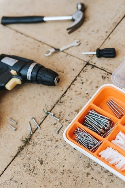
Assembling your Pooboo exercise bike typically requires a few common tools, though some models may include them. A set of metric Allen wrenches is essential for securing most bolts and components.

An adjustable wrench or socket set can be helpful for certain connections. A Phillips head screwdriver may also be needed. It’s recommended to have a rubber mallet for gently tapping parts into place, and a level to ensure stable positioning.

Components and Parts Identification

Understanding the parts of your Pooboo exercise bike is crucial for assembly and maintenance. Key components include the frame and base, providing structural support. The resistance system, vital for workout intensity, varies by model.

The console and monitor display workout metrics. Familiarize yourself with these parts – frame, base, resistance components, console, seat, handlebars, pedals, and any included accessories – before beginning assembly. Refer to diagrams in your specific model’s manual.

Frame and Base Components

The Pooboo exercise bike’s frame, typically constructed from alloy steel, provides the primary structural integrity. The base ensures stability during intense workouts, often featuring leveling feet for uneven surfaces. Examine these components for any shipping damage before assembly;

Key parts include the main frame tubes, base supports, and footpads. Proper alignment of these components is essential for a secure and comfortable riding experience. Ensure all bolts are tightened according to the assembly instructions.

Resistance System Components

Pooboo exercise bikes utilize various resistance mechanisms, often including a magnetic resistance system for smooth and quiet operation. Key components are the flywheel, resistance knob or adjustment lever, and the magnetic brake pad assembly.

The flywheel’s weight influences the ride’s feel, while the resistance control allows users to customize workout intensity. Regularly inspect the brake pad for wear and ensure proper alignment to maintain consistent resistance levels throughout your fitness journey.

Console and Monitor Features

The Pooboo exercise bike console displays crucial workout metrics, including speed, distance, time, and estimated calories burned. Many models feature heart rate monitoring, either through hand-grip sensors or wireless chest straps (sold separately).

The console often includes pre-programmed workout routines and customizable settings. Familiarize yourself with the button functions and display indicators for optimal tracking and a more engaging exercise experience. Ensure proper battery installation or power connection for consistent operation.

Operating the Pooboo Exercise Bike

Before starting, ensure the bike is stable and all parts are securely fastened. Power on the console and complete the initial setup, if prompted. Adjust the seat height and handlebar position for a comfortable and efficient riding posture.

Begin with a low resistance level and gradually increase it as your fitness improves. Maintain a consistent cadence and proper form throughout your workout. Always use caution when starting and stopping the exercise bike.

Powering On and Initial Setup

To power on, locate the power button on the console. The display will illuminate, potentially prompting for user data like age, weight, and height – input accurately for calorie and distance calculations. Some models may require battery installation.

Familiarize yourself with the console’s interface before commencing your workout. Ensure the console correctly displays your initial settings. If issues arise, consult the troubleshooting section of this manual.

Adjusting Seat and Handlebar Positions

Proper positioning is crucial for comfort and effective workouts. Locate the adjustment levers beneath the seat and handlebars. Loosen these levers to slide the seat forward or backward, and adjust the handlebars vertically.

Ensure your legs have a slight bend at the bottom of the pedal stroke and your back is supported. Retighten the levers securely after each adjustment. Regularly check tightness during use to prevent shifting.

Understanding the Console Display

The Pooboo console provides real-time workout data. Key metrics displayed include speed, measuring your pedaling rate; distance, tracking your total workout length; time, showing elapsed workout duration; and calories, estimating energy expenditure.

Many models also feature heart rate monitoring, often via hand pulse sensors. Familiarize yourself with the console’s buttons for navigating menus and resetting data between sessions for accurate tracking.

Key Metrics Displayed (Speed, Distance, Time, Calories)

The console prominently displays crucial workout data. Speed is shown in MPH or KPH, indicating your pedaling intensity. Distance tracks your cumulative progress, often in miles or kilometers. Time accurately measures your workout duration, essential for interval training.

Calories provide an estimate of energy burned, aiding in fitness goal tracking. Understanding these metrics empowers you to monitor performance and adjust your workout accordingly.

Heart Rate Monitoring Features

Pooboo exercise bikes may incorporate heart rate monitoring for optimized workouts. Some models feature hand pulse sensors built into the handlebars, providing real-time heart rate readings during exercise. Wireless chest straps (sold separately) offer more accurate and continuous monitoring.

Tracking your heart rate helps you stay within your target heart rate zone, maximizing calorie burn and improving cardiovascular fitness. Utilize this feature to personalize your training intensity.

Resistance Adjustment

Pooboo exercise bikes typically offer manual resistance adjustment mechanisms. A tension knob, often located near the flywheel, controls the resistance level. Clockwise rotation increases resistance, simulating uphill climbs or higher intensity workouts, while counter-clockwise decreases it.

Experiment with different resistance levels to find the optimal challenge for your fitness goals. Start with lower settings and gradually increase as your strength and endurance improve, ensuring a comfortable and effective workout.

Manual Resistance Levels

Pooboo bikes utilize a friction-based system for manual resistance. The tension knob directly affects the brake pads’ pressure against the flywheel, dictating workout intensity. Higher numbers generally equate to greater resistance, demanding more effort from the rider.

Beginners should start with lower resistance levels, gradually increasing as fitness improves. Consistent adjustments throughout a workout allow for interval training, simulating varied terrain and maximizing calorie burn. Remember to fully tighten the knob for secure resistance.

Maintenance and Care

Regular upkeep extends your Pooboo bike’s lifespan and ensures optimal performance. Cleaning involves wiping down the frame and console with a damp cloth, avoiding harsh chemicals. Periodically inspect all bolts and screws, tightening as needed to prevent loosening during use.

Lubricate the chain and moving parts to maintain smooth operation and reduce noise. Consistent care prevents premature wear and tear, safeguarding your investment and providing a reliable fitness experience.

Cleaning and Lubrication

Maintaining a clean Pooboo bike is crucial for longevity. Wipe down the frame, handlebars, and console regularly with a soft, damp cloth. Avoid abrasive cleaners that could damage the finish. For the resistance system, periodically apply a silicone-based lubricant to the chain and related components.

This reduces friction and ensures smooth, quiet operation. Inspect for dust buildup and remove it to prevent wear. Proper lubrication safeguards against corrosion and extends the bike’s functional life.

Regular Inspection of Parts

Consistent inspection is vital for safe and effective use of your Pooboo exercise bike. Regularly check all bolts and screws to ensure they are tightened securely – especially those connecting the frame, seat, and handlebars. Examine the resistance system for any signs of wear or damage.

Inspect the console display and heart rate sensors for proper functionality. Address any loose parts or unusual noises immediately to prevent potential issues and maintain optimal performance.

Troubleshooting Common Issues

Encountering problems with your Pooboo bike? Addressing console errors promptly is key; try resetting the device or checking power connections. If noise develops during operation, inspect for loose bolts or worn components, and tighten or replace as needed.

For persistent issues, consult the full manual or online support resources. Don’t attempt repairs beyond your skill level, as this could void the warranty or create safety hazards.

Addressing Console Errors

If the console displays an error message, first attempt a simple reset by powering the bike off and on again. Ensure all connections are secure, particularly the power cable and any sensor wires. Check the battery compartment if applicable, replacing batteries if low.

For recurring errors, consult the comprehensive manual for specific error code definitions and troubleshooting steps. Contact Pooboo support if the issue persists, providing the model number and error details.

Fixing Noise Problems

Unusual noises during operation often indicate loose components. Systematically check all bolts and screws on the frame, resistance system, and console, tightening as needed. Apply lubricant to the chain and other moving parts, following the maintenance schedule in this manual.

If squeaking persists, inspect the seat and handlebar posts for proper tightening. Contact Pooboo support if the noise continues, detailing the type and location of the sound.

Warranty Information

Pooboo offers a warranty covering manufacturing defects on its exercise bikes. The specific coverage duration varies by model, but generally includes the frame, parts, and labor. Warranty does not cover normal wear and tear, misuse, or damage caused by improper assembly.

To claim warranty service, retain your proof of purchase and contact Pooboo customer support. Detailed warranty terms and conditions are available on the official Pooboo website.

Pooboo Warranty Coverage Details

Pooboo’s warranty typically covers the frame for a substantial period, often exceeding one year, protecting against structural failures. Parts are usually covered for a shorter duration, like 90 days to one year, addressing defects in components. Labor costs for repairs during the initial warranty period are also included.

The warranty is voided by unauthorized modifications or commercial use. Customers are responsible for shipping costs related to warranty claims. Refer to the official Pooboo documentation for precise details.

Frequently Asked Questions (FAQ)

Q: What if the console isn’t displaying correctly? A: Ensure the power adapter is securely connected and try resetting the console. Q: How often should I lubricate the bike? A: Lubricate the chain and joints monthly to maintain smooth operation. Q: Can I use the bike for extended periods? A: Yes, but take breaks and listen to your body.

Q: Where can I find replacement parts? A: Contact Pooboo’s customer support or check authorized retailers. Q: What’s the weight capacity? A: Refer to your specific model’s specifications.

Where to Find Additional Support

For immediate assistance, contact Pooboo’s dedicated customer support team via their official website. Explore online forums and communities dedicated to Pooboo exercise bikes for user-shared tips and troubleshooting advice. Check the official Pooboo website for downloadable manuals, FAQs, and instructional videos.

Authorized retailers may also offer support and assistance. Utilize social media platforms to connect with other Pooboo users and seek guidance. Remember to have your model number readily available when contacting support.

old kohler generator manuals

Old Kohler Generator Manuals: A Comprehensive Guide

This guide delves into the world of Kohler generator documentation‚ tracing its evolution alongside the company’s history from 1873.
It’s a resource for owners seeking information on both current and discontinued models‚ navigating the recent transition to Kohler Energy under Platinum Equity’s ownership.

Understanding Kohler Generator History & Ownership

Kohler’s journey began in 1873‚ evolving from a cast iron and steel foundry into a global powerhouse encompassing diverse businesses‚ including generators. Initially‚ documentation likely mirrored the era – potentially sparse‚ focused on mechanical aspects‚ and lacking the detailed safety protocols of today.

Over decades‚ as Kohler generators became more sophisticated‚ so did their manuals. The company’s long-standing commitment to quality and innovation‚ built on “honest and fair behavior‚” likely influenced the increasing comprehensiveness of these guides.

Recently‚ a significant shift occurred with the establishment of Kohler Energy as an independent entity under Platinum Equity’s majority ownership (January 26‚ 2023). While Kohler Co. remains an investment partner‚ understanding this ownership change is crucial when sourcing manuals‚ as support structures may evolve.

The Transition to Kohler Energy (Platinum Equity)

The recent separation of Kohler’s Energy business‚ with Platinum Equity becoming the majority owner in January 2023‚ introduces a key consideration for owners of older Kohler generators seeking manuals. While Kohler Co. retains an investment role‚ the direct line for manual access and support may be shifting.

Historically‚ Kohler Co. centralized manual distribution. Now‚ it’s vital to determine whether Kohler Energy will maintain the same archive accessibility for legacy models. This transition could impact the availability of physical copies and online downloads.

Owners should proactively verify the current official channels for obtaining manuals‚ noting any changes in website addresses or contact information. Understanding this ownership shift is paramount when troubleshooting or performing maintenance on older units‚ ensuring access to accurate documentation.

Kohler Co.: A Historical Overview (Founded 1873)

Founded in 1873‚ Kohler Co.’s long-standing history is intrinsically linked to the evolution of its generator products and‚ consequently‚ the documentation surrounding them. Beginning with entrepreneurial innovation‚ the company grew into one of America’s largest privately held businesses‚ boasting over 40‚000 associates.

This extensive history means a vast range of generator models have been produced over the decades‚ each potentially requiring specific manuals. Understanding Kohler’s commitment to quality and ethical leadership‚ established since its inception‚ suggests a historical emphasis on comprehensive product support‚ including detailed documentation.

However‚ the sheer age of some generators necessitates diligent searching for older manuals‚ as digital archives may not encompass every model produced throughout Kohler’s 150+ year history. Knowing the company’s origins aids in contextualizing the search.

Locating Manuals: Key Resources

Finding manuals for older Kohler generators requires a multi-faceted approach. Primary resources include the official Kohler website‚ which maintains a digital archive‚ though coverage of very old models may be limited. Supplementing this are third-party archives and online databases specializing in vintage equipment documentation.

Successfully locating a manual often hinges on accurately identifying the generator’s model number. This number is crucial for targeted searches across these resources. Furthermore‚ exploring forums and online communities dedicated to Kohler generators can yield valuable leads and shared documentation from fellow enthusiasts.

Remember to verify the manual’s applicability to your specific generator model before relying on its information.

Official Kohler Website & Manual Downloads

The official Kohler website serves as the first port of call for locating generator manuals. While the focus is naturally on current models‚ a dedicated section provides access to downloadable documentation for many older units. Navigating the site requires knowing your generator’s specific model number for a targeted search.

Kohler’s online archive is regularly updated‚ but coverage of manuals for extremely old or discontinued generators may be incomplete. Users may encounter situations where a direct download isn’t available‚ necessitating contact with Kohler support. The website also offers helpful resources for understanding generator features and maintenance.

Always prioritize downloading manuals directly from Kohler to ensure authenticity and accuracy.

Third-Party Manual Archives & Online Databases

Beyond the official Kohler website‚ several third-party archives and online databases can be valuable resources for locating old generator manuals. These platforms often host user-submitted documentation‚ filling gaps where Kohler’s official archive is lacking. However‚ caution is advised when using these sources‚ as the accuracy and completeness of the manuals cannot always be guaranteed.

Popular options include dedicated generator forums‚ online parts retailers that archive manuals‚ and general document-sharing websites. Always verify the manual’s model number against your generator to ensure compatibility. Cross-referencing information with the official Kohler documentation‚ when available‚ is highly recommended.

Remember to scan downloaded files for viruses before opening them.

Kohler Generator Model Number Identification

Accurately identifying your Kohler generator’s model number is crucial for locating the correct manual. This number is typically found on a metal plate affixed to the generator’s frame. Look for a label often near the engine or control panel‚ containing alphanumeric characters. Older models may have a stamped-in number‚ potentially requiring cleaning to reveal.

The model number distinguishes specific generator configurations and features‚ ensuring you download the appropriate documentation. Without it‚ you risk using a manual for a different generator‚ leading to incorrect information and potential safety hazards. Record the serial number as well‚ as it can be helpful for warranty claims or contacting Kohler support.

Carefully transcribe the number to avoid errors during your search.

Types of Kohler Generators & Corresponding Manuals

Kohler manufactures a diverse range of generators‚ each requiring specific documentation. Residential standby generators‚ designed for automatic home backup‚ have manuals focusing on installation‚ transfer switches‚ and maintenance schedules. Commercial generators‚ built for businesses and critical facilities‚ feature manuals detailing complex electrical systems and load management.

Portable generators‚ offering temporary power solutions‚ have simpler manuals emphasizing safe operation and basic maintenance. Older models may have fewer detailed diagrams compared to newer ones. Locating the correct manual depends on identifying the generator type and model number. Kohler’s historical product line includes variations within each category‚ necessitating precise identification.

Manuals often categorize generators by fuel type (gasoline‚ propane‚ diesel) and kilowatt output.

Residential Standby Generators: Manual Focus

Manuals for Kohler residential standby generators prioritize automatic operation and seamless power restoration during outages. Key sections detail installation procedures‚ including gas line connections and electrical wiring to the home’s transfer switch. Emphasis is placed on safety precautions regarding fuel handling and carbon monoxide risks.

Older manuals may lack the detailed digital schematics found in newer versions‚ but still cover essential maintenance like oil changes‚ air filter replacements‚ and battery checks. Troubleshooting guides address common issues like starting failures and low voltage. Understanding the transfer switch functionality is crucial‚ and manuals provide diagrams and explanations.

Regular maintenance‚ as outlined in the manual‚ extends the generator’s lifespan and ensures reliable performance.

Commercial Generators: Manual Specifics

Kohler commercial generator manuals differ from residential guides‚ focusing on continuous operation and higher power demands. They detail complex electrical systems‚ including three-phase power configurations and voltage regulation. Installation instructions emphasize compliance with commercial building codes and safety regulations.

Older manuals often include extensive wiring diagrams for connecting to building management systems and automatic transfer switches. Maintenance schedules are more rigorous‚ covering coolant levels‚ belt inspections‚ and fuel filter replacements. Troubleshooting sections address issues like engine overheating and generator overload.

Understanding the generator’s control panel and its various settings is vital for optimal performance and longevity.

Portable Generators: Manual Variations

Kohler portable generator manuals prioritize user-friendliness and straightforward operation‚ differing significantly from those for standby or commercial units. Older versions often feature simplified diagrams and instructions geared towards occasional use and easy transport. Safety sections emphasize carbon monoxide hazards and proper ventilation.

Manuals typically cover basic maintenance like oil changes‚ spark plug replacements‚ and air filter cleaning. Troubleshooting focuses on common issues like starting difficulties and power output fluctuations. Variations exist based on engine size and features like electric start or inverter technology.

Locating the correct manual is crucial‚ as models can share similar appearances but have distinct internal components.

Decoding Kohler Generator Manual Sections

Kohler generator manuals‚ even older editions‚ generally follow a consistent structure. Initial sections detail safety precautions and warnings – critically important for preventing injury and damage. Installation guides outline proper setup‚ grounding‚ and fuel connection procedures.

Operation sections explain starting‚ running‚ and shutting down the generator‚ alongside load management advice. Maintenance schedules are vital‚ detailing fluid checks‚ filter replacements‚ and inspection intervals. Troubleshooting guides offer solutions to common problems‚ often with diagnostic flowcharts.

Diagrams and exploded views illustrate component locations and assembly. Understanding these sections unlocks effective generator ownership and longevity.

Safety Precautions & Warnings

Old Kohler generator manuals consistently emphasize safety as paramount. Carbon monoxide poisoning is a critical concern; operation must occur outdoors in well-ventilated areas. Electrical hazards are also prominent – proper grounding and adherence to electrical codes are non-negotiable.

Fuel handling requires extreme caution‚ avoiding spills and ensuring proper storage away from ignition sources. Hot surfaces on the engine pose burn risks‚ necessitating protective gear. Manuals warn against improper modifications or overloading the generator‚ which can lead to failure or fire.

Always disconnect the spark plug before performing maintenance. Ignoring these warnings can result in severe injury or death.

Installation & Setup Instructions

Old Kohler generator manuals detail site preparation as crucial for successful installation. This includes ensuring a level‚ stable surface capable of supporting the generator’s weight. Manuals emphasize proper ventilation and clearances from structures and combustible materials.

Fuel line connections and exhaust system installation are covered with specific diagrams and torque specifications. Electrical connections require adherence to local codes‚ including grounding procedures. Manuals often include wiring diagrams for various configurations.

Initial startup procedures involve checking fluid levels and verifying all connections before engaging the engine. Following these steps ensures safe and reliable operation.

Operation & Maintenance Procedures

Old Kohler generator manuals meticulously outline routine maintenance schedules. These typically include regular oil and filter changes‚ air filter cleaning or replacement‚ and inspection of belts and hoses. Manuals stress the importance of using Kohler-approved fluids and parts to maintain warranty validity and optimal performance.

Operational guidelines cover load management‚ emphasizing avoiding overloading the generator. Manuals detail proper shutdown procedures to prevent engine damage. Periodic inspections of the exhaust system and electrical connections are also highlighted.

Scheduled maintenance‚ as per the manual‚ extends the generator’s lifespan and ensures reliable power during outages.

Troubleshooting Common Issues (Using Manuals)

Old Kohler generator manuals are invaluable for diagnosing and resolving common problems. Manuals typically dedicate sections to starting difficulties‚ often detailing checks for fuel supply‚ spark plug condition‚ and battery health. Electrical output issues are addressed with voltage regulation troubleshooting steps.

Manuals guide users through identifying potential causes for overheating‚ low oil pressure‚ or unusual noises. They emphasize safety precautions before attempting any repairs. Diagrams and exploded views aid in identifying components and understanding their function.

Referencing the manual before contacting support can often resolve minor issues quickly and efficiently‚ saving time and expense.

Starting Problems & Solutions

Old Kohler generator manuals consistently address starting issues as a primary troubleshooting concern. Common problems include a flooded engine‚ a weak battery‚ or a faulty starter solenoid. Manuals detail procedures for priming the carburetor‚ checking the fuel lines for obstructions‚ and testing the battery’s voltage.

They often include diagrams illustrating the ignition system and provide steps for inspecting the spark plug. Manuals emphasize the importance of using the correct choke settings and following the recommended starting procedure. Solutions range from simple adjustments to component replacement.

Referencing the specific manual for your model is crucial‚ as procedures can vary.

Electrical Output & Voltage Regulation

Old Kohler generator manuals dedicate significant sections to understanding electrical output and maintaining stable voltage. They explain the generator’s capacity in watts and volts‚ detailing safe load limits to prevent damage. Manuals illustrate the Automatic Voltage Regulator (AVR) system and its role in ensuring consistent power delivery‚ even with fluctuating loads.

Troubleshooting guides within the manuals address issues like low voltage‚ voltage spikes‚ and frequency deviations. They provide instructions for testing the AVR‚ checking wiring connections‚ and verifying the output voltage with a multimeter. Understanding these systems is vital for safely powering sensitive electronics.

Proper maintenance‚ as outlined in the manuals‚ is key to reliable performance.

Oil & Fluid Level Checks & Maintenance

Old Kohler generator manuals consistently emphasize the critical importance of regular oil and fluid level checks for longevity. They detail specific oil types and viscosities recommended for each model‚ alongside capacities for quick reference. Manuals provide step-by-step instructions for safely checking oil levels using the dipstick‚ and coolant levels in liquid-cooled models.

Maintenance schedules within the manuals outline oil change intervals‚ often based on operating hours. They also cover procedures for flushing the cooling system‚ inspecting hoses‚ and checking for leaks. Proper fluid maintenance prevents engine wear and ensures optimal performance. Referencing these guides is essential for preventative care.

Ignoring these checks can lead to catastrophic engine failure.

Manuals for Discontinued Kohler Generator Models

Locating manuals for older‚ discontinued Kohler generators can present a challenge‚ but isn’t impossible. Original printed manuals often aren’t readily available‚ necessitating exploration of alternative resources. Kohler’s historical documentation‚ while extensive‚ doesn’t always cover every model extensively online. However‚ third-party archives and online databases frequently host scanned copies of these older guides.

The key is accurate model number identification‚ as this unlocks access to the correct documentation. Even manuals for similar‚ slightly newer models can provide valuable insights into operation and maintenance. Understanding Kohler’s evolution‚ particularly the transition to Kohler Energy‚ aids in finding relevant information. Persistence and diligent searching are often required.

Finding Manuals for Older‚ Rare Models

Securing documentation for truly rare or older Kohler generator models demands a resourceful approach. Official Kohler resources may have limited information‚ requiring exploration beyond the primary website. Online forums dedicated to generators and small engines often host user-shared manuals and troubleshooting tips. Consider contacting specialized vintage engine parts suppliers; they frequently possess archived documentation.

Utilizing similar model manuals as a reference point can prove invaluable‚ focusing on core operational principles. Remember Kohler’s long history – even pre-Platinum Equity – means documentation exists somewhere. Networking with experienced mechanics or generator enthusiasts can unlock hidden resources. Patience is crucial‚ as locating these manuals often requires dedicated effort and community collaboration.

Using Similar Model Manuals as a Reference

When a specific manual for your older Kohler generator proves elusive‚ leveraging documentation from comparable models can be remarkably effective. Focus on generators sharing the same engine type or those produced within a similar timeframe. Core operational procedures – oil checks‚ filter replacements‚ and basic troubleshooting – often remain consistent across generations.

However‚ exercise caution; electrical diagrams and specific component layouts will differ. Always prioritize safety and avoid assumptions. Refer to the similar model manual as a guide‚ not a definitive source. Cross-reference information whenever possible and consult experienced mechanics if unsure. Understanding Kohler’s historical engineering principles aids in interpreting these resources effectively.

Understanding Kohler Generator Schematics & Diagrams

Kohler generator manuals frequently include detailed schematics and diagrams crucial for repair and maintenance. These visuals depict electrical wiring‚ fuel systems‚ and component placement. Understanding these diagrams requires a basic grasp of electrical symbols and mechanical layouts. Older manuals may feature less clarity‚ necessitating careful study.

Pay close attention to wire colors‚ connector types‚ and component labeling. Exploded views illustrate how parts assemble‚ aiding in disassembly and reassembly. Diagrams are essential for diagnosing electrical faults and performing accurate repairs. Remember that variations exist between models; always use the diagram specific to your generator’s model number. Proper interpretation minimizes errors and ensures safe operation.

Electrical Wiring Diagrams Explained

Kohler generator electrical wiring diagrams are foundational for troubleshooting and repair. These diagrams illustrate the flow of electricity through the generator’s system‚ showing connections between components like the alternator‚ voltage regulator‚ and control panel. Understanding common symbols – representing wires‚ resistors‚ and connectors – is vital. Older manuals may use simpler‚ less standardized notations.

Trace circuits carefully‚ noting wire gauges and colors. Pay attention to grounding points‚ crucial for safety. Diagrams often depict safety devices like circuit breakers and fuses. Always disconnect the generator from power before working on electrical systems. Refer to the manual for specific wiring configurations for your model. Accurate interpretation prevents damage and ensures safe operation.

Parts Lists & Exploded Views

Kohler generator manuals frequently include detailed parts lists and exploded views‚ essential for repairs and maintenance. These lists provide part numbers‚ descriptions‚ and quantities needed for assembly or replacement. Exploded views graphically depict how components fit together‚ simplifying disassembly and reassembly. Older manuals may lack the clarity of modern diagrams‚ requiring careful study.

Utilize part numbers when ordering replacements to ensure compatibility. Cross-reference with current Kohler parts catalogs‚ as some older parts may be superseded. Pay attention to revision levels of parts lists‚ as updates occur. These views are invaluable when troubleshooting‚ identifying worn or damaged components. Proper use minimizes downtime and extends generator lifespan.

The Importance of Regular Maintenance (Referencing Manuals)

Consistent maintenance‚ guided by your Kohler generator manual‚ is crucial for reliability and longevity. Kohler’s history‚ dating back to 1873‚ emphasizes quality‚ but even the best generators require care. Manuals outline scheduled tasks – oil changes‚ filter replacements‚ and inspections – preventing costly repairs. Ignoring maintenance voids warranties and reduces efficiency.

Refer to the manual for specific intervals and procedures tailored to your model. Platinum Equity’s recent acquisition of Kohler Energy reinforces the need to maintain value through proper care. Regular checks‚ as detailed in the manual‚ identify potential issues early. Proactive maintenance ensures your generator is ready when needed‚ safeguarding power during outages.

Scheduled Maintenance Tasks

Kohler generator manuals detail specific maintenance schedules‚ varying by model and usage. Typically‚ these include monthly checks of oil and coolant levels‚ alongside air filter inspections. Every 50-100 hours‚ oil and filter changes are recommended‚ alongside fuel filter replacements. Annual tasks encompass spark plug checks‚ battery testing‚ and a thorough inspection of wiring and connections.

For older models‚ referencing similar manuals can supplement missing information‚ given Kohler’s long history since 1873. Platinum Equity’s ownership doesn’t alter these fundamental maintenance needs. Adhering to these schedules‚ as outlined in the manual‚ maximizes generator lifespan and ensures optimal performance. Proper maintenance prevents unexpected failures and costly repairs‚ safeguarding reliable power.

Extending Generator Lifespan

Consistent adherence to the maintenance schedules detailed in your Kohler generator manual is paramount for longevity. Regular oil and filter changes‚ utilizing Kohler-approved products‚ minimize internal wear. Protecting the generator from the elements – rain‚ snow‚ and extreme temperatures – prevents corrosion and damage. Proper storage during extended periods of inactivity‚ including fuel stabilization‚ is crucial.

Even with older‚ discontinued models‚ referencing similar manuals and Kohler’s historical commitment to quality (since 1873) aids in preventative care. Platinum Equity’s recent acquisition doesn’t diminish the importance of these practices. Diligent upkeep‚ guided by the manual‚ maximizes the generator’s operational life‚ ensuring years of reliable power‚ and avoiding premature replacement.

Kohler Generator Manuals & Warranty Information

Original Kohler generator manuals often contain crucial warranty details‚ though coverage periods have evolved since the company’s founding in 1873. Locating the manual is the first step in understanding any remaining warranty protection‚ even for older units. However‚ warranties are typically non-transferable and have expiration dates.

The recent transition to Kohler Energy under Platinum Equity may affect warranty support for some models. Contacting Kohler support directly‚ referencing the generator’s model number‚ is essential to verify current warranty status. While older manuals may not reflect current policies‚ they provide a baseline for understanding initial coverage terms. Maintaining records of maintenance‚ as outlined in the manual‚ can sometimes support warranty claims.

Warranty Coverage & Manual Requirements

Historically‚ Kohler generator warranty coverage has varied based on the model and purchase date‚ with details outlined in the accompanying manual. For older generators‚ especially those predating the 2023 transition to Kohler Energy‚ warranty periods are likely expired. However‚ proof of ownership and the original manual can be beneficial when contacting Kohler support.

Manuals often specify required maintenance schedules; adherence to these may have been a condition of the original warranty. While Kohler Co. maintains records‚ the manual serves as primary documentation. Platinum Equity’s ownership may influence current warranty policies‚ so referencing the manual alongside direct communication with Kohler is crucial. Understanding the manual’s terms is key to assessing any potential‚ albeit limited‚ coverage.

Contacting Kohler Support

When seeking assistance with older Kohler generators‚ direct contact with Kohler support is essential‚ despite potential documentation challenges. The official Kohler Co. website provides corporate contact information‚ including phone numbers and addresses for global locations. However‚ due to the recent transition to Kohler Energy under Platinum Equity‚ specifying the generator’s age and model number is crucial for routing your inquiry correctly.

Having the generator’s manual‚ even a partial or photocopied version‚ will significantly aid the support team. Be prepared to provide proof of ownership if possible. While support for discontinued models may be limited‚ Kohler representatives can often offer guidance on parts sourcing or troubleshooting based on similar‚ current models. Utilize their expertise to navigate potential issues.

fire lite ecc 50/100 manual

Fire Lite ECC-50/100 Manual: A Comprehensive Overview (12/16/2025)

This manual details the Fire Lite ECC-50/100 system, offering guidance on installation, programming, operation, and maintenance for optimal fire safety performance․

The Fire Lite ECC-50/100 represents a cornerstone in modern fire alarm control panel technology, designed for a broad spectrum of applications – from small commercial spaces to larger, more complex facilities; This manual serves as a comprehensive resource for anyone involved in the installation, programming, operation, or maintenance of these systems․

Understanding the capabilities of the ECC-50/100 is crucial for ensuring reliable fire detection and notification․ The system’s architecture allows for flexible configuration, accommodating various initiating devices like smoke detectors and pull stations, alongside notification appliances such as horns and strobes․

As of December 16, 2025, staying current with best practices and adhering to the guidelines outlined within this document will maximize the system’s effectiveness and contribute to life safety․ This introduction sets the stage for a detailed exploration of each component and function․

What is the Fire Lite ECC-50/100 System?

The Fire Lite ECC-50/100 system is a fully programmable, addressable fire alarm control panel (FACP) designed to mitigate risks associated with fire emergencies․ It functions as the central hub, receiving signals from initiating devices and activating notification appliances to alert occupants․ The system’s core strength lies in its adaptability, supporting a wide range of fire detection and suppression technologies․

NASA’s LANCE FIRMS data highlights the importance of rapid fire detection, a capability the ECC-50/100 directly addresses․ It’s engineered for reliability and ease of use, offering features like zone configuration and sensitivity adjustments․

Beyond basic functionality, the ECC-50/100 can integrate with other building systems, enhancing overall safety and security․ Understanding its role within a broader fire protection strategy is paramount for effective implementation․

Key Features and Benefits

The Fire Lite ECC-50/100 boasts several key features, including advanced programming capabilities, allowing for customized system configurations tailored to specific building needs․ Its addressable technology pinpoints the exact location of an alarm, reducing response times – a critical factor, as demonstrated by Bulloch County Fire’s focus on minimizing their 10m18s average response time․

Benefits include enhanced reliability, simplified troubleshooting, and reduced false alarms through sensitivity adjustments․ The system’s compatibility with diverse initiating and notification devices offers flexibility․

Furthermore, the ECC-50/100 supports real-time fire activity monitoring, aligning with NASA’s LANCE FIRMS data provision․ This proactive approach to fire safety ensures a swift and effective response, protecting lives and property․

System Components

The Fire Lite ECC-50/100 system comprises control panels, remote annunciators, initiating devices like smoke detectors, and notification appliances such as horns and strobes․

Control Panel (ECC-50/100)

The ECC-50/100 control panel serves as the central hub of the fire alarm system, receiving signals from initiating devices and activating notification appliances․ It’s designed for both small and large applications, offering flexible zoning capabilities to pinpoint fire locations quickly․

Key features include a microprocessor-based design for reliable operation, a large LCD display for clear system status, and extensive event logging for detailed analysis․ The panel supports various communication options, enabling remote monitoring and reporting․ Programming is achieved through a user-friendly interface, allowing customization of system parameters to meet specific site requirements․

Proper installation and wiring are crucial for optimal performance, adhering to all applicable codes and standards․ Regular maintenance, including battery checks and system walk tests, ensures continued reliability and responsiveness․

Remote Annunciators

Fire Lite ECC-50/100 systems can integrate with remote annunciators, providing a secondary display of system status in geographically separated locations․ These annunciators mirror the control panel’s information, including zone identification, alarm status, and trouble conditions․

They are particularly useful in large facilities where immediate access to the main control panel is impractical․ Annunciators offer a visual indication of alarm events, enabling quicker response times․ Wiring to the control panel is typically achieved using a dedicated communication bus, ensuring reliable data transmission․

Proper configuration is essential to ensure accurate mirroring of system events․ Regular testing of the annunciator’s functionality is recommended to verify its operational readiness and maintain system integrity․

Initiating Devices (Smoke Detectors, Heat Detectors, Pull Stations)

The Fire Lite ECC-50/100 system supports a wide range of initiating devices crucial for early fire detection․ These include addressable smoke detectors, designed to identify airborne particles indicative of combustion, and heat detectors, responding to significant temperature increases․ Manual pull stations allow for immediate alarm activation by building occupants․

Compatibility with various detection technologies ensures adaptability to diverse environments․ Proper device placement, adhering to NFPA guidelines, is vital for optimal performance․ Each initiating device is assigned a unique address within the system, facilitating precise location identification during an alarm event․

Regular inspection and testing of all initiating devices are essential to verify their sensitivity and operational reliability․

Notification Appliances (Horns, Strobes)

The Fire Lite ECC-50/100 system utilizes notification appliances – horns and strobes – to alert building occupants to fire emergencies․ Horns produce audible warnings, while strobes provide visual signals, crucial for individuals with hearing impairments․ These devices are synchronized by the control panel to ensure a coordinated and easily recognizable alarm pattern․

The system supports various candela settings for strobes, allowing for appropriate visibility based on room size and ambient light levels․ Proper placement of notification appliances, adhering to ADA guidelines, is essential for effective evacuation․

Regular testing of horns and strobes verifies their functionality and audibility/visibility․ Compatibility with the ECC-50/100 ensures reliable operation during critical events․

Installation and Wiring

Proper installation and wiring are critical for the Fire Lite ECC-50/100 system’s reliability․ Follow all national and local codes for safe and effective operation․

Mounting the Control Panel

Securely mounting the Fire Lite ECC-50/100 control panel is paramount for its functionality and longevity․ Choose a central, easily accessible indoor location, protected from physical damage and environmental factors like excessive humidity or temperature fluctuations․

The panel should be mounted on a flat, solid surface using appropriate hardware – screws and anchors suitable for the wall type․ Ensure sufficient clearance around the panel for wiring access and future maintenance․

Adhere to the manufacturer’s specified mounting height recommendations, typically between 4 and 6 feet from the floor․ Verify the mounting surface can support the panel’s weight, especially when fully loaded with batteries and modules․ Proper grounding is essential; connect the panel’s ground terminal to a verified earth ground․

Wiring Diagrams for Initiating Devices

Proper wiring of initiating devices – smoke detectors, heat detectors, and pull stations – is crucial for reliable fire detection․ The Fire Lite ECC-50/100 utilizes a Class B Initiating Device Circuit (IDC) wiring configuration․

Typically, devices are wired in a loop, often referred to as a “single-pair” circuit․ Each device connects to the next, forming a continuous path back to the control panel․ End-of-line resistors (EOLRs) are essential; they monitor the circuit integrity and signal any tampering or faults․

Refer to the detailed wiring diagrams provided in the appendix for specific device configurations․ Ensure correct polarity and wire gauge are used, adhering to local electrical codes․ Incorrect wiring can lead to false alarms or system failures․ Always disconnect power before making any wiring changes․

Wiring Diagrams for Notification Appliances

Notification appliance circuits (NACs) on the Fire Lite ECC-50/100 control panel activate horns, strobes, and other audible/visual alarms․ These circuits are typically Class A, requiring separate wiring for each device or zone․ However, the ECC-50/100 also supports Class B wiring for reduced conductor count․

Wiring diagrams detail the specific configurations for both Class A and Class B NACs․ Pay close attention to the voltage and current requirements of your chosen notification appliances․ Ensure proper synchronization of strobes to avoid seizures, as mandated by ADA guidelines․

Always consult the diagrams for correct wiring polarity and use appropriate wire gauge․ Incorrect wiring can damage the control panel or appliances․ Disconnect power before any wiring modifications․ Proper grounding is essential for reliable operation and safety․

Power Supply Connections

The Fire Lite ECC-50/100 requires a reliable power source for continuous operation․ It utilizes a 120VAC primary power input, typically connected through a dedicated circuit․ A secondary, 24VDC battery backup system ensures functionality during power outages․ Proper battery maintenance is crucial, as detailed in the maintenance section․

Wiring diagrams illustrate the correct connections for both AC power and the battery charger․ Ensure the correct polarity when connecting the battery; reverse polarity can cause severe damage․ Use appropriately sized wiring to handle the current draw․

Grounding the control panel is essential for safety and proper operation․ Verify the voltage of the battery backup system regularly․ A failing battery will trigger a trouble signal on the panel․

Programming and Configuration

The ECC-50/100’s programming allows customization of zone configurations, sensitivity adjustments, and system walk test procedures for tailored fire protection․

Entering Programming Mode

To access the programming mode on the Fire Lite ECC-50/100 control panel, begin by ensuring the system is in a normal, non-alarm state․ Locate the programming keypad – typically integrated into the control panel itself․ Press and hold the “Enter” or “Program” key (refer to the panel’s specific labeling) for a designated duration, usually three to five seconds․

The panel will then prompt for a valid access code․ This code, crucial for security, is often pre-set during initial installation but can be modified by authorized personnel․ Consult the installation documentation or a qualified technician if the default code is unknown․ Upon successful code entry, the display will indicate that the system is now in programming mode, allowing for configuration adjustments․

Zone Configuration

Zone configuration within the Fire Lite ECC-50/100 dictates how the system interprets signals from initiating devices․ Each zone represents a specific physical area, allowing for precise alarm location identification․ Access the zone configuration menu through the programming mode․ Here, you can assign device types – smoke detectors, heat detectors, pull stations – to individual zones․

Crucially, define each zone’s characteristics: normal, alarm, or trouble․ Sensitivity settings can also be adjusted per zone, optimizing performance for specific environments․ Proper zone mapping is vital for effective emergency response; ensure accurate representation of the building layout․ Save changes after configuration to activate the new zone settings within the system․

Sensitivity Adjustments

Adjusting detector sensitivity on the Fire Lite ECC-50/100 is crucial for minimizing false alarms while ensuring rapid fire detection․ Access sensitivity settings through the programming mode, navigating to the specific detector’s configuration․ Higher sensitivity levels increase responsiveness to smoke or heat, but also raise the risk of nuisance alarms from cooking or dust․

Lowering sensitivity reduces false alarms but may delay detection․ Carefully consider the environment when making adjustments․ Regularly test detectors after sensitivity changes using the system walk test․ Document all adjustments for future reference and troubleshooting․ Optimal sensitivity balances responsiveness and reliability, tailored to each protected area․

System Walk Test Procedures

Performing a system walk test on the Fire Lite ECC-50/100 verifies proper operation of all initiating and notification devices․ Initiate the test from the control panel’s programming mode․ Systematically activate each detector (smoke, heat, pull station) and observe corresponding annunciator and audible alarm responses․

Confirm that each device triggers the correct zone and alarm signals․ Document any discrepancies or failures immediately․ Walk the entire protected area, ensuring all notification appliances (horns, strobes) activate as expected․ A successful walk test confirms the system’s ability to reliably detect and alert occupants to a fire emergency․ Repeat tests periodically and after any system changes․

Operation and Maintenance

Regular maintenance ensures reliable Fire Lite ECC-50/100 performance․ This includes routine inspections, battery checks, and prompt troubleshooting of any system faults or alarms․

Normal System Operation

During typical operation, the Fire Lite ECC-50/100 control panel continuously monitors all connected initiating devices – smoke detectors, heat detectors, and pull stations – for any signs of fire or system distress․ A green “System Normal” LED indicator confirms the panel is powered and functioning correctly, with all zones reporting as clear․

The system performs self-diagnostics, checking for wiring faults, device tamper conditions, and communication issues․ Any detected issues are logged and may trigger a yellow “Trouble” indicator․ Regular walk tests, as outlined in the programming section, verify proper communication between the panel, remote annunciators, and notification appliances (horns and strobes)․

The panel’s logic ensures that only legitimate alarm signals initiate a full-scale evacuation, minimizing false alarms․ Understanding these normal operating conditions is crucial for effective system management and response․

Alarm Indication and Response

Upon detecting a fire condition, the Fire Lite ECC-50/100 immediately activates audible and visual notification appliances․ A red “Alarm” LED illuminates on the control panel, and the specific zone(s) in alarm are clearly indicated on the display․ Simultaneously, the panel initiates pre-programmed sequences, potentially including relay activation for remote alarm monitoring or fire department notification․

The system’s response is dictated by the programmed cause-and-effect matrix․ This matrix defines which devices activate which outputs based on the initiating device and zone․ Personnel should immediately verify the alarm source, following established emergency procedures․

Silence alarm conditions only after confirming the situation is safe․ Detailed alarm logs provide valuable information for post-incident analysis and system optimization․

Battery Maintenance and Replacement

The Fire Lite ECC-50/100 relies on backup batteries to maintain operation during power outages․ Regular inspection – at least annually – is crucial․ Check for corrosion, swelling, or any physical damage to the batteries․ Verify battery voltage using a multimeter, ensuring it remains within the manufacturer’s specified range․

When replacing batteries, always use the type recommended by Fire Lite․ Incorrect battery types can damage the system or compromise its reliability․ Disconnect the main power supply before handling batteries․ Properly dispose of old batteries according to local regulations․

Record battery replacement dates for future reference․ A fully charged battery ensures uninterrupted system functionality during emergencies․

Troubleshooting Common Issues

Common issues with the Fire Lite ECC-50/100 often involve false alarms or system faults․ First, check the initiating devices – smoke detectors or pull stations – for dust or obstructions․ Verify zone configurations in the programming mode to ensure correct device assignments․

If a trouble signal appears, consult the system’s event log for specific details․ Low battery voltage is a frequent cause; address this immediately․ Wiring issues can also trigger faults; inspect connections carefully․ A slow response time from Bulloch County Fire highlights the importance of a functioning system․

For persistent problems, contact a qualified Fire Lite technician for assistance․ Do not attempt repairs beyond your expertise․

Advanced Features & Data

The ECC-50/100 integrates with external data sources, like NASA’s LANCE FIRMS, for enhanced fire activity monitoring and historical analysis capabilities․

Fire Data from NASA LANCE FIRMS

The Fire Lite ECC-50/100 system can be integrated with data provided by NASA’s LANCE Fire Information for Resource Management System (FIRMS)․ This allows for near real-time active fire data, sourced from both MODIS and VIIRS sensors, to be incorporated into the system’s monitoring capabilities․

FIRMS provides valuable information for firefighters and those tracking fire activity․ Users can access downloadable data or utilize a map interface to visualize fire locations and intensity․ Subscription-based email alerts, tailored to specific areas of interest, are also available․ This integration enhances situational awareness, enabling quicker and more informed responses to potential fire threats․ The system benefits from the continuous updates and comprehensive coverage offered by NASA’s FIRMS platform․

Global Fire Map Analysis

Utilizing data from sources like NASA’s FIRMS, the Fire Lite ECC-50/100 system facilitates comprehensive global fire map analysis․ This capability allows users to explore past fire seasons and understand the interplay between weather patterns, landscape features, and active fire incidents․

The system’s interface provides tools to visualize fire activity across different regions, identifying hotspots and tracking fire spread․ This analysis is crucial for proactive fire prevention and resource allocation․ By examining historical data, users can identify trends and assess potential risks․ The integration of global fire maps enhances the ECC-50/100’s ability to provide a holistic view of fire threats, supporting informed decision-making and improved fire safety protocols․

Real-Time Fire Activity Monitoring

The Fire Lite ECC-50/100 system, when integrated with NASA’s LANCE FIRMS, offers robust real-time fire activity monitoring capabilities․ This feature provides up-to-the-minute data on active fires, sourced from MODIS and VIIRS satellite imagery; Users can quickly assess current fire situations and respond effectively․

The system’s interface displays fire locations, intensity, and progression, enabling rapid situational awareness․ Customizable alerts can be set up to notify personnel of new fire detections within specific areas of interest․ This proactive approach is vital for minimizing damage and ensuring swift response times․ Real-time monitoring empowers users to stay informed and make critical decisions based on the latest available information, enhancing overall fire safety․

Historical Fire Season Data

The Fire Lite ECC-50/100 system facilitates access to valuable historical fire season data, complementing real-time monitoring with long-term trends․ Analyzing past fire activity patterns is crucial for proactive risk assessment and resource allocation․ This data, often sourced alongside NASA’s LANCE FIRMS, reveals seasonal variations and potential hotspots․

Users can examine fire frequency, intensity, and geographic distribution over previous years, identifying areas prone to recurring incidents․ This historical perspective informs preventative measures, such as targeted vegetation management and enhanced fire prevention campaigns․ By understanding past fire seasons, organizations can better prepare for future events, optimizing their response strategies and minimizing potential losses;

FIRE Movement & Financial Implications

While unrelated to the system’s function, the FIRE movement’s focus on financial independence mirrors the ECC-50/100’s goal of providing security and peace of mind․

Economic Freedom (FIRE) Calculation

Interestingly, calculating FIRE – Financial Independence, Retire Early – shares a conceptual similarity with assessing fire safety system needs․ Both involve evaluating resources and risks․ FIRE calculations typically center around the “4% rule,” suggesting withdrawing 4% of your investment portfolio annually can sustain you indefinitely․

However, this is a simplification․ Like a fire system’s design, a FIRE plan requires careful consideration of individual circumstances․ Factors include expected expenses, investment returns, and longevity․ Just as a Fire Lite ECC-50/100 system’s cost depends on building size and occupancy, a FIRE number is highly personalized․

Tools like the “Ekonomisk frihet (FIRE)-kalkylator” help estimate this number, mirroring how system design software aids in determining appropriate fire protection levels․ Both emphasize proactive planning for future security․

Achieving Financial Independence

Similar to ensuring a robust fire safety system, achieving financial independence demands diligent planning and consistent effort․ The FIRE movement emphasizes maximizing savings and investments to create passive income streams․ This parallels the proactive installation of smoke detectors and sprinkler systems – preventative measures for future security․

Strategies include minimizing expenses, increasing income, and strategically investing in assets․ Just as a Fire Lite ECC-50/100 system requires regular maintenance, a FIRE portfolio needs ongoing monitoring and adjustments․ Anonymity regarding finances is common, mirroring the discreet nature of security systems․

Success stories demonstrate the feasibility of early retirement, highlighting the power of disciplined financial habits․ Like a well-maintained fire system providing peace of mind, financial independence offers freedom and control․

Anonymity and FIRE

Maintaining financial privacy is a recurring theme within the FIRE community, akin to the discreet operation of a Fire Lite ECC-50/100 system․ Many individuals intentionally avoid publicizing their wealth, preferring to keep financial details confidential from colleagues and acquaintances․

This preference stems from various motivations, including security concerns and a desire to avoid unwanted attention․ Just as a fire alarm system operates silently until triggered, personal finances are often shielded from public view․ The emphasis is on building wealth without external validation․

This approach fosters a focus on intrinsic goals rather than societal expectations, mirroring the reliable, behind-the-scenes functionality of a fire safety system․ It’s about personal freedom and control, much like a properly configured and maintained ECC-50/100 panel․

Long-Term FIRE Success Stories

Similar to the enduring reliability of a Fire Lite ECC-50/100 system, long-term FIRE success hinges on consistent planning and diligent execution․ Stories emerge of individuals who achieved financial independence years ago and continue to thrive, adapting to changing circumstances․

These narratives often highlight the importance of flexible strategies and ongoing maintenance – akin to regular system walk tests and battery checks․ Successful FIRE adherents emphasize the need to reassess investments and adjust spending as life evolves․

They demonstrate that FIRE isn’t a static endpoint but a dynamic lifestyle, much like a fire panel constantly monitoring for potential threats․ These stories inspire others, proving that sustained financial freedom is attainable with foresight and commitment․

windmill ac manual

Windmill AC Manual: A Comprehensive Guide

This manual details windmill AC systems, transforming wind energy into electricity. Modern turbines, often called windmills, utilize rotating blades and generators.
Historically, windmills ground grain, but now power our lives.

Windmill AC systems represent a pivotal advancement in renewable energy technology, harnessing the kinetic energy of wind and converting it into usable alternating current (AC) electricity. These systems, often referred to as wind turbines by engineers and windmills by the general public, are becoming increasingly prevalent as a sustainable alternative to traditional fossil fuel-based power generation.

The core principle behind these systems is remarkably simple: wind turns propeller-like blades, rotating a rotor connected to a generator. This generator then transforms the mechanical energy of the spinning rotor into electrical energy. However, the journey from wind to usable AC power involves a series of sophisticated components and control mechanisms.

Historically, windmills served primarily for mechanical tasks like grinding grain, a practice dating back centuries. Today, they’ve evolved into complex machines capable of powering homes, businesses, and even entire communities. Understanding the intricacies of these systems – from the rotor blades to the grid connection – is crucial for efficient operation, maintenance, and future development. This guide provides a comprehensive overview of windmill AC systems, covering their components, functionality, and emerging trends.

Historical Overview of Windmills and AC Generation

The story of windmills stretches back centuries, initially serving as mechanical devices for tasks like grinding grain into flour – a cornerstone of bread production. These early windmills, utilizing sails mounted on a rotating shaft, transformed wind’s force into rotational motion, powering essential processes for communities worldwide. Their design cleverly divided wind force into components, maximizing rotational efficiency.

However, the leap to AC (Alternating Current) generation is a relatively recent development. While windmills existed for millennia, the ability to convert wind energy into electricity didn’t materialize until the advent of electromagnetic induction and the development of generators in the 19th century. Early wind turbines, appearing in the late 1800s and early 1900s, were often small-scale, powering individual homes or farms.

The modern era witnessed significant advancements, particularly with the introduction of grid-connected wind farms. These large-scale installations leverage sophisticated AC systems, including rectifiers, inverters, and transformers, to efficiently deliver power to the electrical grid. The evolution from simple grain grinders to complex AC power producers demonstrates a remarkable technological journey.

Understanding the Basic Components of a Windmill AC System

A functional windmill AC system comprises several key interconnected components, working in harmony to convert wind energy into usable electricity. At its heart lies the wind turbine itself, capturing the kinetic energy of the wind through its rotor blades. This rotational energy is then transferred to a generator housed within the nacelle.

The generator is crucial, converting mechanical energy into electrical energy, initially in the form of DC (Direct Current). However, for efficient transmission and grid compatibility, this DC power undergoes conversion via an inverter, transforming it into AC. A rectifier may also be present to ensure proper DC flow. Voltage levels are then adjusted by a transformer to match grid requirements.

Beyond these core elements, sophisticated control systems are essential. These systems utilize wind speed sensors (anemometers) to monitor wind conditions and adjust blade pitch and yaw orientation for optimal performance. Safety mechanisms, like over-speed protection and lightning arrestors, safeguard the system from damage. Ultimately, these components collaborate to deliver clean, renewable energy.

The Wind Turbine: Core of the System

The wind turbine stands as the central element of any windmill AC system, responsible for initially capturing the kinetic energy present in the wind. Unlike a fan which uses electricity to create wind, a wind turbine cleverly utilizes wind to generate electricity – a fundamental distinction. This is achieved through propeller-like blades connected to a rotor.

As wind flows across these blades, it imparts rotational force, spinning the rotor and, consequently, a connected generator. The turbine’s design is critical; modern iterations build upon designs dating back to the 1890s, with some employing multiple sails (up to 18) to maximize energy capture even in low wind conditions. These sails are angled to divide the wind’s force, efficiently converting it into rotational motion.

The turbine’s effectiveness relies on a delicate balance of aerodynamic principles and mechanical engineering. It’s a testament to how a relatively simple concept – harnessing wind power – has evolved into a sophisticated technology for sustainable energy production.

Rotor Blades: Design and Function

Rotor blades are the primary interface between the wind and the wind turbine, meticulously engineered to capture maximum kinetic energy; Their design isn’t arbitrary; blades are mounted at a specific angle or possess a slight twist. This crucial feature divides the force of the wind into components, with one component directly driving rotation – the key to electricity generation.

Modern turbines often feature multiple blades, reminiscent of designs from the 1890s, where up to 18 sails were employed. This configuration enhances the turbine’s ability to start rotating even in low wind speeds, effectively ‘catching’ the breeze. The blades’ shape and curvature are optimized using aerodynamic principles, maximizing lift and minimizing drag.

The materials used in blade construction are also vital, requiring strength, flexibility, and resistance to weathering. Efficient blade design directly translates to increased energy output, making them a critical component in the overall performance of a windmill AC system.

Nacelle: Housing the Generator and Control Systems

The nacelle is the protective housing situated atop the wind turbine tower, encapsulating the critical components responsible for converting wind energy into usable electricity. It’s essentially the ‘brain’ and ‘powerhouse’ of the entire system, shielding sensitive equipment from the elements.

Within the nacelle resides the generator, the device that transforms mechanical energy from the rotating rotor into electrical energy. Crucially, the nacelle also houses sophisticated control systems. These systems continuously monitor wind speed, direction, and turbine performance, making real-time adjustments to optimize energy capture.

These control systems manage vital functions like yaw control (aligning the turbine with the wind) and pitch control (adjusting blade angles). Furthermore, the nacelle contains essential safety mechanisms, such as over-speed protection, preventing damage during excessively high winds. Access for maintenance and repairs is also integrated into the nacelle’s design, ensuring long-term operational reliability.

Generator: Converting Mechanical Energy to Electrical Energy

The generator is the heart of the windmill AC system, responsible for the pivotal conversion of mechanical energy – derived from the rotating rotor blades – into electrical energy. This transformation is based on the principles of electromagnetic induction, a fundamental concept in physics.

As the rotor spins, it turns a shaft connected to the generator. Inside the generator, coils of wire rotate within a magnetic field. This relative motion induces an electric current within the wires, creating alternating current (AC) electricity. The type of generator used can vary, including synchronous and asynchronous designs, each with its own characteristics.

The generated AC electricity then undergoes further processing via components like rectifiers, inverters, and transformers to ensure it meets the required voltage and frequency standards for grid connection or direct use. The efficiency and reliability of the generator are paramount to the overall performance of the windmill AC system, dictating the amount of usable power produced.

Tower: Supporting the Wind Turbine

The tower is a critical structural element of any windmill AC system, providing the necessary elevation for the wind turbine to access stronger, less turbulent wind currents. Tower height significantly impacts energy production; higher towers generally yield greater efficiency.

These towers are engineered to withstand immense forces, including wind loads, the weight of the nacelle and rotor, and potential environmental stressors like ice and lightning. Common tower types include tubular steel, lattice, and concrete structures, each suited to different site conditions and turbine sizes.

The foundation of the tower is equally important, requiring robust design to anchor the structure securely to the ground. Careful geological surveys are essential to ensure foundation stability. Access for maintenance personnel is also a key consideration in tower design, often incorporating internal ladders or lifts. A well-designed tower ensures the long-term reliability and operational lifespan of the entire windmill AC system.

AC Electrical System Components

The AC electrical system is the heart of a windmill’s power delivery, converting the mechanical energy captured by the turbine into usable electricity. This system comprises several key components working in harmony to ensure efficient and reliable power generation.

Initially, the generator produces AC electricity, which often requires conditioning. A rectifier converts this AC power to DC, facilitating voltage control and compatibility with downstream components. Subsequently, an inverter transforms the DC power back into AC, synchronizing it with the grid’s frequency and voltage.

Transformers play a crucial role in stepping up the voltage for efficient transmission across power lines. Control systems continuously monitor and adjust these components, optimizing performance and ensuring grid stability. Protective devices, like circuit breakers and surge arrestors, safeguard the system from faults and transient events. Proper integration and maintenance of these components are vital for maximizing energy output and minimizing downtime.

The Role of the Rectifier in AC Conversion

The rectifier is a critical component within a windmill’s AC electrical system, bridging the gap between the generator’s output and the inverter’s input. Wind turbines initially generate alternating current (AC) electricity, but many control and transmission systems operate more efficiently with direct current (DC).

The rectifier’s primary function is to convert this AC power into DC power. This conversion is achieved using diodes, semiconductor devices that allow current to flow in only one direction. By arranging these diodes strategically, the rectifier ensures a unidirectional current flow, effectively transforming the alternating waveform into a steady DC voltage.

This DC output is then smoothed and filtered to minimize ripple and provide a stable power source for the inverter. The rectifier’s efficiency and reliability are paramount, as any losses or failures here directly impact the overall system performance. It’s a foundational step in harnessing wind energy for practical applications.

Inverter: Converting DC to AC

Following rectification, the DC power generated by the windmill requires conversion back into alternating current (AC) for most practical applications, particularly grid connection and powering standard electrical devices. This crucial task is performed by the inverter.

The inverter utilizes sophisticated electronic switching circuits, typically employing transistors like IGBTs (Insulated Gate Bipolar Transistors), to rapidly switch the DC voltage on and off, creating an alternating waveform. Modern inverters employ Pulse Width Modulation (PWM) techniques to precisely control the output voltage and frequency, ensuring compatibility with grid standards.

The quality of the AC output – its waveform, frequency, and voltage – is paramount. Inverters must minimize harmonic distortion and maintain a stable frequency (typically 50 or 60 Hz) to avoid damaging connected equipment or disrupting the power grid. Advanced inverters also offer grid synchronization capabilities, ensuring seamless power delivery.

Transformer: Voltage Regulation for Grid Connection

After the inverter converts DC power back to AC, the voltage level often needs adjustment to match the grid’s requirements. This is where the transformer plays a vital role. Wind turbine generators produce variable voltage depending on wind speed, making direct grid connection impractical without voltage regulation.

Transformers are static devices employing electromagnetic induction to step up or step down voltage levels. In wind turbine applications, they typically step up the relatively low voltage generated by the turbine to the higher voltages used in transmission and distribution networks. This minimizes current, reducing transmission losses.

The transformer’s core is constructed from laminated steel to minimize eddy current losses, while the windings are carefully designed to achieve the desired voltage ratio. Modern wind farms often utilize multiple transformers, including both unit transformers (connected to individual turbines) and collection substation transformers (aggregating power from multiple units). Proper transformer sizing and cooling are crucial for reliable operation.

Control Systems: Monitoring and Optimization

Modern windmill AC systems rely heavily on sophisticated control systems for optimal performance and safety. These systems continuously monitor various parameters, including wind speed, direction, generator output, and grid conditions, making real-time adjustments to maximize energy capture.

Key components include wind speed sensors (anemometers) and wind direction sensors, providing crucial data for yaw and pitch control. The control system utilizes algorithms to align the turbine with the wind (yaw control) and adjust blade angles (pitch control) to optimize aerodynamic efficiency.

Advanced systems incorporate Supervisory Control and Data Acquisition (SCADA) for remote monitoring and control. SCADA allows operators to track performance, diagnose faults, and implement preventative maintenance. Furthermore, control systems implement safety mechanisms, such as over-speed protection and grid fault detection, ensuring reliable and safe operation. Data analysis from these systems helps refine turbine performance over time.

Wind Speed Sensors (Anemometers)

Anemometers are critical components within a windmill AC system, responsible for accurately measuring wind speed. This data is fundamental for the control system to optimize turbine performance and ensure safe operation. Typically, cup anemometers are employed, featuring rotating cups that spin proportionally to wind velocity. The rotation rate is then converted into an electrical signal.

More advanced systems utilize ultrasonic anemometers, which measure wind speed based on the time it takes for sound waves to travel between transducers. These offer higher accuracy and require less maintenance than traditional cup anemometers. Accurate wind speed readings are essential for initiating turbine startup, adjusting blade pitch, and implementing over-speed protection mechanisms.

Data from anemometers directly influences the yaw and pitch control systems, maximizing energy capture. Regular calibration and maintenance of anemometers are vital to ensure reliable data and prevent inaccurate control decisions. The control system relies on this information to respond to changing wind conditions effectively.

Yaw Control: Aligning with the Wind

Yaw control is the mechanism responsible for orienting the wind turbine rotor into the wind, maximizing energy capture. This is achieved by rotating the nacelle – the housing containing the generator and other components – horizontally around the tower. A yaw drive motor, controlled by the system’s control unit, executes these rotations.

The control system utilizes data from the wind speed sensors (anemometers) and a wind direction sensor (wind vane) to determine the optimal yaw position. When the turbine is misaligned with the wind, the yaw motor activates, adjusting the nacelle’s position. Precise yaw control is crucial for efficiency, preventing energy loss due to suboptimal wind exposure.

Modern yaw systems often incorporate braking mechanisms to hold the nacelle securely in position during high winds or maintenance. Active yaw control continuously adjusts the turbine’s alignment, while passive systems rely on tail vanes. Regular inspection and maintenance of the yaw drive, motor, and braking systems are essential for reliable operation and longevity.

Pitch Control: Optimizing Blade Angle

Pitch control is a vital function within a windmill AC system, regulating the angle of the rotor blades relative to the wind. This adjustment directly impacts the turbine’s power output and operational safety. By altering the pitch, the system can maximize energy capture at lower wind speeds and prevent damage during high wind events.

Hydraulic or electric actuators, controlled by the central control system, precisely adjust the blade angles. At lower wind speeds, blades are pitched to maximize lift and rotational force. As wind speed increases, pitch control feathers the blades, reducing their angle of attack and limiting power generation to prevent overloading the generator.

Furthermore, pitch control plays a critical role in over-speed protection. In extreme wind conditions, blades can be fully feathered, effectively stopping the rotor and preventing catastrophic failure. Regular inspection and calibration of the pitch system are paramount, ensuring accurate and responsive blade adjustments for optimal performance and turbine longevity.

Safety Mechanisms in Windmill AC Systems

Windmill AC systems incorporate multiple safety mechanisms to ensure reliable and hazard-free operation. These systems protect against both mechanical and electrical failures, safeguarding the turbine, grid, and personnel. Robust design and redundant systems are key to minimizing downtime and preventing costly repairs.

Over-speed protection is crucial, preventing the turbine from exceeding its maximum rotational speed. This is often achieved through blade pitch control, feathering the blades to reduce wind capture, and aerodynamic brakes. Lightning protection systems, including grounding and surge arrestors, divert potentially damaging electrical currents.

Additional safety features include vibration monitoring, temperature sensors, and emergency shutdown systems. Regular inspections, preventative maintenance, and adherence to safety protocols are essential. These mechanisms work in concert to create a resilient and dependable energy generation system, mitigating risks associated with wind power.

Over-Speed Protection

Over-speed protection is paramount in windmill AC systems, preventing catastrophic failure due to excessive rotational velocity. High winds can easily drive a turbine beyond its design limits, leading to structural damage and potential collapse. Multiple layers of protection are therefore implemented to mitigate this risk.

Pitch control is a primary defense, actively adjusting blade angles to reduce aerodynamic forces. Feathering the blades, turning them edge-on to the wind, dramatically slows rotation. Aerodynamic brakes, deploying spoilers on the blades, provide additional drag. Mechanical brakes, typically disc brakes, offer a final, independent stopping mechanism.

Sophisticated control systems continuously monitor wind speed and turbine RPM, initiating protective measures automatically. Redundancy is built-in, ensuring that a single point of failure doesn’t compromise safety. Regular testing and maintenance of these systems are vital for reliable operation, safeguarding the turbine and surrounding environment.

Lightning Protection

Wind turbines, due to their height and exposed location, are highly susceptible to lightning strikes. A robust lightning protection system is therefore crucial for ensuring the safety and operational longevity of a windmill AC system. Direct strikes can cause significant damage to the blades, nacelle, and electrical components.

The primary defense is a Faraday cage principle, where conductive materials create a path for lightning current to flow safely to ground, bypassing sensitive equipment. This involves grounding the turbine tower, blades (often with embedded conductive strips), and nacelle components.

Down conductors, heavy-duty cables, connect these points to a grounding network buried deep within the earth. Surge protection devices (SPDs) are installed on electrical lines to divert transient voltage spikes. Regular inspection and maintenance of the grounding system are essential, verifying low resistance and continuous conductivity. Proper bonding minimizes potential differences and prevents arcing, safeguarding the entire system.

Grid Connection and Synchronization

Successfully integrating a windmill AC system with the electrical grid requires precise synchronization and adherence to stringent grid codes. The generated AC electricity must match the grid’s voltage, frequency, and phase sequence before connection is permitted. This process prevents damage to both the turbine and the grid infrastructure.

Synchronization is typically achieved using sophisticated power electronics, including inverters and transformers. The inverter converts the variable frequency AC output from the generator into a stable, grid-compatible frequency (e.g;, 50 or 60 Hz). The transformer then steps up the voltage to match the grid’s transmission level;

Grid protection relays monitor grid parameters and automatically disconnect the turbine in case of anomalies, such as voltage fluctuations or frequency deviations. Compliance with local utility regulations and safety standards is paramount. Regular testing and commissioning ensure seamless and reliable grid integration, maximizing energy delivery and system stability.

Troubleshooting Common Issues

Windmill AC systems, while robust, can experience operational challenges. Common issues include low power output, often stemming from insufficient wind speed or blade damage. Inspect blades for cracks or debris, and verify anemometer functionality for accurate wind data.

Generator malfunctions can manifest as unusual noises or overheating. Check for bearing wear, loose connections, and proper cooling. Inverter failures may present as erratic voltage or frequency output; examine cooling fans and input/output signals.

Grid synchronization problems can cause turbine shutdowns. Confirm proper voltage and frequency matching, and inspect protection relays for tripping. Lightning strikes pose a significant threat; ensure lightning protection systems are intact and functioning correctly. Regular inspections, preventative maintenance, and detailed record-keeping are crucial for swift diagnosis and resolution of these issues, minimizing downtime and maximizing energy production.

Maintenance Schedule for Windmill AC Systems

A proactive maintenance schedule is vital for optimal performance and longevity. Monthly inspections should focus on visual checks of blades, tower, and nacelle for damage or wear. Lubricate bearings and moving parts quarterly to reduce friction and prevent failure.

Semi-annual maintenance requires a thorough generator inspection, including winding resistance checks and brush replacement (if applicable). Examine the inverter for cooling fan operation and clean heat sinks. Annually, conduct a comprehensive electrical system inspection, verifying all connections are secure and corrosion-free.

Every three to five years, professional blade inspections are recommended to detect internal damage. Tower integrity should also be assessed. Implement a detailed record-keeping system to track maintenance activities and identify recurring issues. Adhering to this schedule minimizes downtime, maximizes energy output, and extends the lifespan of your windmill AC system.

Future Trends in Windmill AC Technology

The future of windmill AC technology is focused on increased efficiency and grid integration. Expect advancements in blade design, utilizing lighter, stronger materials and aerodynamic improvements to capture more wind energy. Larger turbines with higher hub heights are becoming prevalent, accessing stronger and more consistent wind resources.

Smart grid technologies will play a crucial role, enabling better synchronization and power quality control. Predictive maintenance, leveraging data analytics and machine learning, will minimize downtime and optimize performance. Floating offshore wind farms are emerging, unlocking vast wind potential in deeper waters.

Further research centers on direct-drive generators, eliminating gearboxes for increased reliability, and improved energy storage solutions to address intermittency. Innovations in control systems will enhance responsiveness to changing wind conditions. These developments promise a more sustainable and reliable energy future powered by advanced windmill AC systems.

cobra walkie talkies manual

Cobra Walkie Talkies Manual: A Comprehensive Guide

Welcome! This guide provides detailed instructions for Cobra walkie talkies‚ covering setup‚ operation‚ troubleshooting‚ and safety. Access PDF manuals online for models like MT800‚ Rx385‚ and CXT565.

Cobra walkie talkies offer a convenient way to stay connected with family and friends‚ boasting ranges up to 3km (2 miles) on select models. These two-way radios‚ like the microTALK series‚ feature 8 main channels and 38 CTCSS privacy codes for clear communication.

This manual serves as a comprehensive resource‚ guiding you through the features and functions of your Cobra radio. Whether you’re using rechargeable or non-rechargeable batteries‚ understanding your device ensures optimal performance. Explore downloadable PDF manuals for specific models – AM245‚ Rx385‚ MT800‚ and CXT565 – to maximize your experience.

Understanding Key Features

Cobra walkie talkies are equipped with features designed for reliable communication. Key among these are channel selection‚ offering multiple frequencies for operation‚ and CTCSS privacy codes‚ minimizing interference from other users. Models boast backlit LCD displays for easy viewing‚ even in low-light conditions.

Understanding range limitations is crucial; advertised distances depend on terrain. The microTALK series utilizes both rechargeable and standard battery options. Familiarize yourself with these features through your model’s PDF manual for optimal performance and a clear understanding of your radio’s capabilities.

Range and Channel Capacity

Cobra walkie talkies typically offer a range of up to 3 km (2 miles)‚ though actual performance varies based on terrain and obstructions. Many models feature 8 main channels‚ providing options to avoid interference. The CXT565‚ for example‚ highlights this capability.

Channel capacity allows users to find clearer frequencies. Remember‚ advertised ranges are optimal; real-world conditions often reduce effective distance. Consult your specific model’s PDF manual for detailed range specifications and channel information to maximize communication effectiveness.

CTCSS Privacy Codes Explained

CTCSS (Continuous Tone-Coded Squelch System) privacy codes aren’t true security features‚ but they filter out transmissions from users not sharing the same code. Cobra radios often offer 38 CTCSS codes. This reduces unwanted chatter‚ enhancing clarity on busy frequencies.

Selecting a code means your radio only receives signals with that specific tone. Both radios must use the same code to communicate. While not preventing eavesdropping‚ CTCSS improves privacy and minimizes interference. Refer to your model’s manual for a complete list of available codes.

Setting Up Your Cobra Walkie Talkie

Initial setup is straightforward! Begin by carefully reviewing your specific model’s manual for detailed instructions. Cobra recommends turning off the radio during battery charging to ensure optimal performance and longevity. Use only the supplied rechargeable batteries and charger to avoid damage.

If using non-rechargeable batteries‚ ensure correct polarity during installation. Familiarize yourself with the LCD display and its icons. Proper setup guarantees clear communication and access to all features. Always prioritize safety when handling batteries and charging equipment.

Charging the Batteries

Proper charging extends battery life! Always utilize the supplied Cobra charger specifically designed for your microTALK radio. Avoid using third-party chargers‚ as they may cause damage or pose a safety risk. Ensure the radio is turned off during the charging process for optimal results.

Charging times vary depending on the battery’s initial state. Monitor the charging indicator light; it typically changes color when fully charged. Disconnect the charger once complete to prevent overcharging and maintain battery health. Refer to your model’s manual for specific charging guidelines.

Installing Batteries (Non-Rechargeable Options)

For models accepting non-rechargeable batteries: Carefully open the battery compartment‚ typically located on the radio’s back. Insert the correct type and number of batteries‚ observing the polarity markings (+ and -) inside the compartment. Incorrect installation can damage the radio and void the warranty.

Ensure batteries are securely seated. Close the battery compartment cover firmly until it clicks into place. Regularly check battery levels and replace them when performance diminishes. Dispose of used batteries responsibly‚ following local regulations for battery recycling.

Basic Operation

Getting Started: Begin by ensuring batteries are correctly installed and charged. Powering On: Locate the power button – usually prominently placed – and press it to activate the radio. The LCD display will illuminate‚ indicating operational status. Channel Selection: Utilize the channel selector knob or buttons to choose your desired channel.

Confirm the selected channel on the display. Adjust the volume using the volume control for clear communication. Remember to test transmission and reception with another radio to verify functionality before relying on it for critical communication.

Powering On and Off

Initiating Operation: To power on your Cobra walkie talkie‚ locate the designated power button‚ typically found on the unit’s face or side. Press and hold this button for a few seconds until the LCD display illuminates‚ confirming activation. Terminating Operation: To power off‚ repeat the process – press and hold the power button until the display goes dark.

Ensure the radio is completely off when not in use to conserve battery life. Some models feature an automatic power-saving mode; consult your specific model’s manual for details.

Selecting Channels

Channel Selection: Your Cobra walkie talkie offers multiple channels for communication. Use the channel selector knob or buttons – typically located on the radio’s front – to navigate through the available options. The LCD display will indicate the currently selected channel number.

Experiment with different channels to find one with minimal interference. Remember that some channels may be pre-programmed or designated for specific purposes. Refer to your model’s manual for channel details and optimal usage.

Advanced Features & Functions

Explore Enhanced Capabilities: Cobra walkie talkies boast features beyond basic transmission. VOX (Voice Operated Exchange) allows hands-free operation – the radio transmits when it detects sound. Utilize the scanning function to automatically search for active channels‚ pausing on any detected transmissions.

These features enhance convenience and efficiency. Consult your specific model’s manual for detailed instructions on activating and customizing these advanced functionalities. Mastering these tools unlocks the full potential of your Cobra radio.

VOX (Voice Operated Exchange) Operation

Hands-Free Communication: VOX enables transmission by simply speaking‚ eliminating the need to press the talk button. Activate VOX through your radio’s menu‚ adjusting the sensitivity level to suit your environment. Lower sensitivity reduces false activations‚ while higher sensitivity picks up quieter voices.

Ensure a quiet background for optimal performance. Some models offer multiple VOX levels. Refer to your specific Cobra walkie talkie manual for detailed setup instructions and troubleshooting tips regarding VOX functionality.

Scanning for Active Channels

Automatic Channel Search: Utilize the scan function to automatically search for channels with ongoing activity. Press the scan button; your Cobra walkie talkie will cycle through all available channels‚ pausing briefly on those with signals. When a signal is detected‚ the scan will stop‚ allowing you to monitor the transmission.

To resume scanning‚ press the scan button again. Remember that scanning doesn’t guarantee clear communication; interference may still occur. Consult your model’s manual for specific scan features and settings.

Troubleshooting Common Issues

Facing problems? If your Cobra walkie talkie won’t power on‚ ensure batteries are correctly installed and charged. Poor reception or a short range can stem from obstructions‚ weak batteries‚ or interference. Try relocating to an open area. Verify channel selection and CTCSS codes are correct.

Refer to your specific model’s manual for detailed troubleshooting steps. Remember to use only the supplied charger and batteries to avoid damage. If issues persist‚ contact Cobra support for assistance.

No Power/Radio Won’t Turn On

Is your Cobra radio unresponsive? First‚ confirm the batteries are installed with correct polarity – a common oversight! Ensure the batteries are fully charged‚ or try a fresh set of new‚ non-rechargeable batteries if applicable. Only use the supplied charger; incorrect chargers can cause damage.

Inspect the battery contacts for corrosion or debris. If the problem continues‚ check the power switch for proper function. A complete lack of response suggests a potential internal issue requiring professional attention.

Poor Reception/Short Range

Experiencing limited range or static? Several factors can impact Cobra walkie talkie reception. Obstacles like buildings‚ trees‚ and hills significantly reduce range. Ensure you’re not operating in a location with heavy interference from other electronic devices.

Verify you’ve selected an open channel and consider utilizing CTCSS privacy codes to minimize interference. Check antenna connections; a loose antenna drastically reduces performance. Battery level also affects transmission power – ensure batteries are fully charged for optimal range.

Safety Precautions

Prioritize safety when using your Cobra walkie talkie! Always use the supplied rechargeable batteries and charger to prevent damage or fire hazards. Never expose batteries to extreme heat or water. Operate the radio in a well-ventilated area‚ and avoid use in hazardous environments.

Turn off the radio while charging. Keep the device away from small children. Follow all local regulations regarding radio communication. Improper use can lead to health risks or legal consequences. Handle with care to ensure longevity and safe operation.

Battery Safety Guidelines

Crucially‚ use only the supplied rechargeable batteries and charger specifically designed for your Cobra microTALK radio. Never mix old and new batteries‚ or different battery types. Dispose of used batteries responsibly‚ following local regulations. Avoid short-circuiting the batteries‚ as this can cause overheating or leakage.

Do not attempt to disassemble or modify the batteries. Charging should occur in a dry‚ well-ventilated location. Inspect batteries for damage before each use. Improper battery handling can pose a significant safety risk.

Operating Environment Considerations

Cobra walkie talkies are designed for reliable communication‚ but performance can be affected by the environment. Avoid operating in extremely wet or corrosive conditions. Excessive dust or direct sunlight may also impact functionality.

Signal range is reduced by obstacles like buildings and terrain. Keep the antenna clear and upright for optimal transmission. Be mindful of potential interference from other electronic devices. Operating temperature limits should be observed to prevent damage to the radio.

Cobra Walkie Talkie Models & Manual Access

Accessing manuals for your Cobra walkie talkie is straightforward. Downloadable PDF versions are readily available online‚ catering to various models including the MT800‚ Rx385‚ CXT565‚ and AM245.

Cobra’s website provides a comprehensive resource for locating manuals specific to your device. Simply search by model number to find the correct documentation. These manuals offer detailed guidance on features‚ operation‚ and troubleshooting‚ ensuring optimal performance from your two-way radio.

Locating Manuals Online (PDF Downloads)

Finding your Cobra walkie talkie manual online is easy! Cobra offers downloadable PDF manuals for radar detectors‚ dash cams‚ and‚ importantly‚ walkie talkies. Navigate to their support section and search by model number – MT800‚ Rx385‚ CXT565‚ AM245‚ or others.

These PDF documents provide comprehensive guides‚ covering everything from basic operation to advanced features. Accessing these resources ensures you have the information needed to maximize your radio’s functionality and enjoy seamless communication.

Specific Model Manuals (MT800‚ Rx385‚ CXT565‚ AM245)

Cobra provides dedicated manuals for popular models. The MT800 manual details its extended range capabilities. The Rx385 guide focuses on user-friendly operation. For the CXT565‚ discover features like NOAA weather alerts. The AM245 manual explains its compact design and channel selection.

Each manual offers specific instructions‚ troubleshooting tips‚ and safety precautions tailored to that model. These resources are readily available as PDF downloads‚ ensuring you have the precise guidance needed for your Cobra walkie talkie.

Understanding PMR 446 Radios

PMR 446 (Private Mobile Radio 446) radios‚ like many Cobra models‚ operate on a license-free frequency. This allows for convenient‚ short-range communication without needing a license from regulatory bodies. These radios are ideal for recreational use‚ such as family outings or events.

Cobra microTALK radios often utilize PMR 446‚ offering simple‚ reliable two-way communication. They feature pre-programmed channels and utilize CTCSS codes for added privacy‚ minimizing interference from other users on the same frequency.

LCD Display Information

The LCD display on your Cobra walkie talkie provides crucial information at a glance. Expect to see indicators for channel number‚ battery life‚ and signal strength. Icons represent active features like VOX operation or scanning mode. Backlighting enhances visibility in low-light conditions.

Symbols may indicate CTCSS code settings or transmission/reception status. Understanding these icons and symbols is key to effectively operating your radio. Refer to your specific model’s manual for a detailed explanation of each display element.

Interpreting Icons and Symbols

Decoding the LCD is vital. A battery icon shows remaining power – low‚ medium‚ or high. Signal strength is indicated by bars; more bars mean a stronger connection. CTCSS code settings are often displayed numerically. A microphone icon signifies VOX mode is active‚ enabling hands-free operation.

Transmission and reception are shown with distinct icons. Scanning is indicated by a rotating arrow. Consult your model’s manual for a complete list and explanation of all icons and symbols‚ ensuring optimal radio usage.

Maintenance and Care

Regular cleaning extends your Cobra walkie talkie’s life. Use a slightly damp cloth to wipe the exterior; avoid harsh chemicals or solvents. Ensure the radio is powered off during cleaning. Inspect battery contacts for corrosion and clean them gently if needed.

For storage‚ remove batteries (if not rechargeable) to prevent leakage. Store the radio in a cool‚ dry place‚ away from direct sunlight and extreme temperatures. Proper care ensures reliable performance and longevity of your Cobra radio.

Cleaning Your Walkie Talkie

Maintaining cleanliness is crucial for optimal performance. Always power off your Cobra walkie talkie before cleaning. Use a soft‚ slightly damp cloth to gently wipe the exterior casing. Avoid abrasive cleaners‚ solvents‚ or excessive moisture‚ as these can damage the device.

Pay attention to crevices around buttons and the antenna connection. For stubborn dirt‚ lightly dampen the cloth with mild soapy water‚ then wipe dry. Never submerge the radio in water. Regular cleaning ensures a hygienic and functional device.

Storage Recommendations

Proper storage extends the life of your Cobra walkie talkie. When not in use‚ remove the batteries – both rechargeable and non-rechargeable – to prevent corrosion and potential damage. Store the radio in a cool‚ dry place‚ away from direct sunlight and extreme temperatures.

Avoid storing near dust or moisture. A protective case or bag is recommended to shield against physical impacts. Ensure the antenna is securely fastened during storage. Regularly check stored radios to confirm battery integrity and overall condition.

hoverboard manual

Hoverboard Manual: A Comprehensive Guide

Welcome! This manual provides essential guidance for safe operation, troubleshooting, and maintenance of your new hoverboard, ensuring a fun and secure riding experience.

Congratulations on acquiring a self-balancing scooter – a hoverboard! This innovative device offers a thrilling and convenient mode of transportation. Before your first ride, carefully review this manual to understand its features, operation, and safety guidelines. Your hoverboard utilizes advanced gyroscopic sensors and motors to maintain balance, providing a unique riding experience.

This guide will walk you through each component, from the power button to the wheel motors, ensuring you’re fully prepared. We’ll cover charging procedures, basic riding techniques, and essential troubleshooting steps. Remember, responsible operation and regular maintenance are key to maximizing your enjoyment and ensuring the longevity of your hoverboard.

Safety Precautions

Prioritize safety! Always wear a helmet, knee pads, and elbow pads when riding your hoverboard. Ride in well-lit, open areas away from traffic and obstacles. Never operate the hoverboard under the influence of drugs or alcohol. Be mindful of your surroundings and other pedestrians.

Inspect your hoverboard before each use, checking for loose parts or damage. Do not exceed the maximum weight limit specified by the manufacturer. Avoid riding on wet or uneven surfaces. Learn to fall safely – practice bending your knees and rolling to minimize injury. Familiarize yourself with the hoverboard’s limitations and ride within your skill level.

Understanding Hoverboard Components

Familiarize yourself with your hoverboard’s key parts. The power button initiates operation, indicated by LED lights showing battery status. Foot pads, equipped with sensors, detect your weight and control movement. Locate the charging port for battery replenishment.

Internally, wheel motors provide propulsion. Understanding these components aids in troubleshooting and maintenance. The chassis provides structural integrity, while internal wiring connects all systems. Regularly inspect these parts for damage or wear. Knowing the function of each element ensures safe and effective operation of your self-balancing scooter.

Power Button and Indicator Lights

The power button is your hoverboard’s primary control. A single press typically activates the device, while a subsequent press shuts it down. Indicator lights provide crucial feedback on the hoverboard’s status. Solid green usually indicates a fully charged battery and operational readiness.

Flashing red often signals a low battery, requiring immediate charging. Other colors or flashing patterns may indicate errors or calibration needs. Pay close attention to these lights before and during operation. Refer to the full manual for a detailed explanation of each light’s meaning, ensuring safe and informed use.

Foot Pads and Sensors

The foot pads are critical for controlling your hoverboard. Integrated pressure sensors within each pad detect your weight and balance, translating this into movement. Ensure your feet are firmly and centrally positioned on the pads for optimal control and stability.

Avoid placing objects or uneven weight distribution on the pads, as this can cause erratic behavior or prevent operation. Regularly inspect the footpads for damage or debris that could interfere with sensor function. Maintaining clean and unobstructed footpads is essential for a safe and responsive riding experience. Proper foot placement is key!

Charging Port

Locate the charging port, typically covered by a rubber flap, on the underside of your hoverboard. Before connecting the charger, ensure the port is clean and free of debris. Gently clean it if necessary, avoiding any liquid ingress.

Only use the provided charger; using incompatible chargers can damage the battery and void your warranty. Insert the charger plug firmly into the port until a secure connection is established. Inspect the port regularly for any signs of damage, such as bent pins or loose connections. A damaged port requires professional repair.

Wheel Motors

Your hoverboard utilizes two independent electric motors, one within each wheel, to provide movement and balance. These motors are powered by the battery and controlled by the internal circuitry based on your weight distribution and foot pressure. Avoid exposing the motors to excessive moisture or impact, as this can cause damage and malfunction.

Regularly check the wheels for any obstructions, like small stones or debris, that could affect motor performance. Loose connections within the motor housing can sometimes cause issues; however, opening the housing should only be done by qualified technicians. Proper motor function is crucial for safe and stable operation.

Charging Your Hoverboard

Proper charging is vital for optimal battery health and performance. Always use the charger specifically designed for your hoverboard model. Inspect the charging port for any damage or debris before connecting the charger. Initial charging may take longer than subsequent charges – allow several hours for a full charge. Avoid overcharging; disconnect the charger once the indicator light signals a full battery.

Charging time varies depending on the battery capacity and charger wattage. Regularly check the charging port for cleanliness and ensure a secure connection. Do not use the hoverboard while it is charging, and store it in a cool, dry place during the charging process to prevent overheating.

Initial Charging Instructions

Before your first ride, fully charge the hoverboard. Connect the provided charger to the charging port, ensuring a secure connection. The initial charge may require a longer duration – typically several hours – to reach full capacity. Monitor the indicator light; it will usually change color (from red to green) when charging is complete.

Do not interrupt the initial charging cycle. Allowing a complete charge from the start optimizes battery lifespan and performance. Inspect the charger and port for any signs of damage before use. Avoid using third-party chargers, as they may not deliver the correct voltage and could damage the battery.

Charging Time and Battery Life

Typical charging time for a hoverboard ranges from 2 to 4 hours, depending on the battery capacity and charger wattage. A fully charged battery generally provides 30 to 60 minutes of continuous use, though this varies based on rider weight, terrain, and speed.

Battery life degrades over time with use and charging cycles. Avoid fully discharging the battery frequently, as this can shorten its lifespan. Store the hoverboard in a cool, dry place when not in use to maximize battery health. Regularly check the battery’s performance and consider replacement if it significantly diminishes.

Charging Port Inspection and Maintenance

Regularly inspect the charging port for any signs of damage, debris, or corrosion. Gently clean the port with a dry, soft cloth to remove dust or dirt. Avoid using liquids or abrasive cleaners, as these can damage the internal components.

Ensure the charger cable is securely connected to both the hoverboard and the power outlet. Do not force the cable into the port. Check for frayed wires or damage to the charger cable itself and replace it if necessary. A damaged charging port can prevent proper charging and potentially pose a safety hazard.

Operation and Riding Techniques

Mastering your hoverboard requires practice and patience. Begin in a spacious, open area, free from obstacles. Power on the device and complete the calibration process as outlined in the manual. Adopt a balanced stance with feet shoulder-width apart, slightly bent knees, and a relaxed posture;

Steering is achieved by subtly shifting your weight in the desired direction. Gentle pressure on the footpads controls speed and momentum. Avoid sudden or jerky movements, as these can disrupt balance. Practice slow, controlled turns before attempting more advanced maneuvers. Always prioritize safety and wear appropriate protective gear.

Powering On and Off

Initiating operation is simple: Press the power button firmly. The indicator lights will illuminate, confirming the system is activating. Ensure the hoverboard is placed on a level surface before attempting to mount. To power off, press and hold the power button for approximately two seconds until the indicator lights extinguish completely.

A single press may only display battery level. Always confirm complete shutdown before dismounting or storing the device. Never attempt to force the power button; if it doesn’t respond, consult the troubleshooting section. Proper powering on and off preserves battery life and ensures safe operation.

Calibration Process

Proper calibration is crucial for optimal performance and balance. If your hoverboard feels unstable or drifts, initiate the calibration process. Place the hoverboard on a perfectly level surface. Press the power button twice in quick succession – the indicator lights will flash, signaling calibration mode.

Remain still and do not step on the board during this process, which typically takes several seconds. Once calibration is complete, the lights will return to their normal operating state. Repeat if necessary, ensuring a consistently level surface. Incorrect calibration can lead to erratic behavior, so precision is key.

Basic Riding Stance and Balance

Maintaining balance is fundamental to a safe and enjoyable hoverboard experience. Begin by standing with feet shoulder-width apart, slightly bent at the knees. Gently step onto the footpads, ensuring your weight is evenly distributed. Keep your core engaged and look straight ahead – this aids in stability.

Small, subtle movements are key; avoid jerky motions. Lean slightly in the direction you wish to travel. Practice shifting your weight gradually to get a feel for the board’s responsiveness. Start in an open area, away from obstacles, and gradually increase your confidence. Remember, practice makes perfect!

Steering and Maneuvering

Steering a hoverboard relies on weight distribution and subtle foot movements. To turn, gently press down with your toes on the footpad corresponding to the direction you want to go. For example, to turn right, apply slight pressure with your right toes. Avoid abrupt or excessive pressure, as this can cause instability.

Practice smooth, controlled turns in a spacious area. Maneuvering requires coordination and anticipation. Look in the direction you intend to travel, as your body will naturally follow your gaze. Gradual weight shifts are more effective than sudden movements. Remember to maintain a slightly bent knee position for optimal balance and control during steering.

Troubleshooting Common Issues

Encountering problems with your hoverboard is common; here’s how to address them. If the hoverboard won’t turn on, check the power button and charging cable connection. A balancing issue often indicates a need for calibration – refer to the ‘Calibration Process’ section. If charging fails, inspect the charging port for debris or damage, ensuring a secure connection.

Persistent beeping sounds can signal low battery or a system error; consult the battery section. Loose connections inside the unit may also cause issues. If problems persist after these checks, consider professional repair. Always prioritize safety and avoid attempting repairs beyond your skill level.

Hoverboard Won’t Turn On

If your hoverboard fails to power on, several factors could be at play. First, verify the power button is pressed firmly and held for a few seconds; Next, check the charging cable – ensure it’s securely connected to both the hoverboard and a functioning power outlet. A completely depleted battery may require a longer initial charge before responding.

Inspect the charging port for any visible damage or obstructions. If the indicator light doesn’t illuminate during charging, the charger itself might be faulty. Try a different outlet to rule out power source issues. If these steps don’t resolve the problem, internal components may require professional attention.

Hoverboard Doesn’t Balance

Difficulty maintaining balance is a common issue, especially for new users. Ensure the hoverboard is fully charged, as low battery levels can affect sensor performance. Begin by practicing in a spacious, open area, preferably on a flat surface. Proper calibration is crucial; follow the calibration process outlined in this manual carefully.

Focus on maintaining a centered stance with slightly bent knees. Avoid leaning too far forward or backward. Loose connections within the hoverboard can also cause balancing problems; consider having it inspected. If the issue persists, the internal sensors might be malfunctioning and require professional repair or replacement.

Hoverboard Won’t Charge

If your hoverboard isn’t charging, several factors could be at play; First, examine the charging port for any visible debris or damage – gently clean it if necessary. Ensure the charger is securely connected to both the hoverboard and a functioning wall outlet. Try a different outlet to rule out power source issues.

Inspect the charger itself for any signs of damage, such as frayed wires. A faulty charger will prevent proper charging. Battery issues are also common; an old or damaged battery may need replacing. If none of these steps resolve the problem, there might be an internal electrical fault requiring professional attention.

Hoverboard Beeping Sounds

Various beeping patterns from your hoverboard indicate different issues. Continuous beeping often signals a low battery, prompting immediate charging. Intermittent beeping could mean the self-balancing system is struggling, potentially due to improper calibration or an uneven surface.

Rapid, repeated beeps frequently indicate a motor malfunction or a loose connection within the internal components. If the beeping occurs while riding, immediately dismount to prevent potential injury. Check for obstructions around the wheels. If the problem persists, professional inspection is recommended to diagnose and repair any underlying electrical or mechanical faults.

Maintenance and Care

Regular maintenance extends your hoverboard’s lifespan and ensures optimal performance. Frequent cleaning with a damp cloth removes dirt and debris, preventing component damage. Inspect the battery regularly; avoid extreme temperatures and fully charge before prolonged storage.

Wheel and tire maintenance involves checking for wear and tear, and cleaning to remove obstructions. Store your hoverboard in a cool, dry place, away from direct sunlight. Avoid water exposure. Periodically check for loose screws or connections. Following these simple steps will keep your hoverboard safe and enjoyable for years to come.

Cleaning Your Hoverboard

Maintaining a clean hoverboard is crucial for its longevity and performance. Use a soft, damp cloth to wipe down the exterior surfaces, removing dirt, dust, and grime. Avoid abrasive cleaners or harsh chemicals, as these can damage the finish.

Pay special attention to the footpads, ensuring they are free of debris. For stubborn marks, a mild soap solution can be used, followed by a thorough wipe with a clean, damp cloth. Never submerge the hoverboard in water or spray it directly with liquids. Ensure the charging port is dry before connecting it to a power source.

Battery Care and Storage

Proper battery maintenance is vital for optimal hoverboard performance and lifespan. Avoid completely draining the battery before recharging; instead, charge it regularly to maintain its health. Store the hoverboard in a cool, dry place, away from direct sunlight and extreme temperatures.

For long-term storage, charge the battery to around 50-60% capacity. Avoid storing a fully charged or fully discharged battery for extended periods, as this can degrade its performance. Periodically check the battery level during storage and recharge as needed. If the battery appears damaged, discontinue use and consult a qualified technician.

Wheel and Tire Maintenance

Regularly inspect the wheels and tires for any signs of wear and tear. Check for cuts, bulges, or embedded debris that could affect performance or safety. Keep the tires clean and free from dirt and grime to maintain optimal grip.

Ensure the wheel motors are free from obstructions. If a wheel isn’t spinning freely, carefully inspect it for any foreign objects. Avoid riding on rough or uneven surfaces for extended periods, as this can accelerate wear. Periodically check the tightness of the wheel axles and secure them if necessary. Replace worn tires promptly to maintain stability and control.

Storage Guidelines

When storing your hoverboard for extended periods, it’s crucial to properly prepare the battery. Charge the battery to approximately 50-60% before storage to prevent damage from over-discharge or overcharging. Store the hoverboard in a cool, dry place, away from direct sunlight and extreme temperatures.

Avoid storing the hoverboard in humid environments, as this can cause corrosion. Cover the hoverboard with a protective cover to prevent dust accumulation. Periodically check the battery level during long-term storage and recharge if necessary. Keep the hoverboard out of reach of children and pets during storage.

Advanced Features (If Applicable)

Some hoverboard models offer Bluetooth connectivity, allowing pairing with smartphones for music playback and app control. Dedicated apps often provide features like remote control, ride statistics tracking, firmware updates, and customizable settings. Speed modes are frequently adjustable, offering options for beginner, standard, and sport riding experiences.

These modes limit the maximum speed to suit rider skill levels. Certain models include self-balancing features or learning modes to assist new users. Explore the app interface to fully utilize these advanced functionalities and personalize your hoverboard experience. Refer to the specific model’s app documentation for detailed instructions.

Bluetooth Connectivity and App Control

Your hoverboard may feature Bluetooth, enabling connection to a dedicated smartphone application. Download the app (name varies by model) from your app store and follow the in-app pairing instructions. Ensure Bluetooth is enabled on both your hoverboard and smartphone. The app unlocks several features, including remote control functionality, allowing operation without physically being on the board.

Ride statistics, such as distance traveled and speed, are often tracked and displayed within the app. Firmware updates can be delivered through the app, improving performance and adding new features. Customize settings like LED light colors and sensitivity adjustments via the app interface for a personalized experience.

Speed Modes and Settings

Many hoverboards offer multiple speed modes designed for varying rider skill levels and environments. Beginner mode typically limits the maximum speed, enhancing stability and control for new users. Standard mode provides a balance between speed and responsiveness, suitable for everyday riding. Sport mode unlocks the hoverboard’s full speed potential, intended for experienced riders in open areas.

Access speed mode settings through the companion app (if applicable) or via a combination of power button presses – consult your model’s specific instructions. Be mindful of local regulations regarding maximum allowable speeds for personal transporters. Always prioritize safety and select a speed mode appropriate for your skill and surroundings.

Warranty Information

Your hoverboard is covered by a limited warranty against defects in materials and workmanship for a period of [Insert Warranty Period — e.g., 180 days] from the date of original purchase. This warranty does not cover normal wear and tear, damage resulting from accidents, misuse, neglect, unauthorized modifications, or improper maintenance.

To make a warranty claim, please contact our customer support team at [Insert Contact Information] and provide proof of purchase, a detailed description of the defect, and any supporting documentation. We reserve the right to repair or replace the defective product at our discretion. Warranty is void if the hoverboard is disassembled or altered by unauthorized personnel.

Frequently Asked Questions (FAQ)

Q: Why won’t my hoverboard turn on? A: Ensure it’s fully charged and the power button is pressed firmly. Check for any damage to the charging port.

Q: What if my hoverboard doesn’t balance? A: Recalibrate the device following the instructions in the ‘Calibration Process’ section. Practice in a safe, open area.

Q: Why is my hoverboard beeping? A: Beeping often indicates a low battery or a system error. Charge the device or consult the ‘Troubleshooting’ section.

Q: How do I properly store my hoverboard? A: Store in a cool, dry place away from direct sunlight. Disconnect the battery for long-term storage.

cessna 172n maintenance manual

Cessna Model 172N maintenance demands diligent adherence to published Service Letters and Service News Letters, ensuring operational reliability and longevity for pilots.

Overview of the Cessna 172N

The Cessna 172N, a cornerstone of general aviation, represents a pivotal evolution within the 172 series, renowned for its robust design and dependable performance. Introduced in 1981, this model boasts several enhancements over its predecessors, including a refined interior and improved engine options, solidifying its position as a favored training and personal aircraft.

Its enduring popularity stems from its forgiving flight characteristics, making it ideal for student pilots, while its versatility caters to recreational flying and light transportation needs. Understanding the 172N’s systems – from the Lycoming engine to the straightforward flight controls – is crucial for effective maintenance. Regular inspections, guided by the official Cessna maintenance manual and supplemental Service Bulletins, are paramount to sustaining airworthiness and preventing costly repairs.

The aircraft’s relatively simple construction facilitates owner-performed maintenance tasks, though adherence to certified mechanics for critical inspections remains essential for safety and regulatory compliance.

Importance of Regular Maintenance

Consistent, meticulous maintenance is absolutely critical for the safe and reliable operation of any Cessna 172N. Neglecting scheduled inspections and preventative measures can lead to component failures, reduced performance, and potentially hazardous flight conditions. Adhering to the Cessna 172N maintenance manual, alongside applicable Airworthiness Directives and Service Bulletins, isn’t merely a regulatory requirement; it’s a commitment to flight safety.

Regular maintenance proactively identifies and addresses wear and tear, preventing minor issues from escalating into major, expensive repairs. This includes diligent monitoring of engine health through oil analysis, thorough inspection of the airframe for corrosion, and consistent servicing of critical systems like brakes and avionics.

Furthermore, detailed logbook entries documenting all maintenance performed are essential for maintaining aircraft value and demonstrating compliance during future inspections. Prioritizing maintenance ensures longevity and maximizes the investment in this popular aircraft.

Scheduled Maintenance Checks

Cessna 172N maintenance schedules encompass annual inspections, 100-hour checks, routine oil changes, and filter replacements, as detailed in the aircraft’s manual.

Annual Inspection Requirements

The annual inspection of a Cessna 172N, as mandated by aviation regulations, is a comprehensive assessment of the aircraft’s airworthiness. This detailed examination, performed by a certified A&P mechanic, ensures continued safe operation. It involves a thorough inspection of the airframe, engine, propeller, landing gear, and all critical systems.

Specifically, the inspection covers structural integrity, control surface functionality, engine performance, and adherence to all applicable Airworthiness Directives (ADs) and Service Bulletins. Mechanics meticulously check for corrosion, cracks, and wear, replacing components as needed. Logbook documentation is crucial, detailing all findings and corrective actions. Proper completion and sign-off of the annual inspection are essential for continued legal flight operations, guaranteeing the aircraft meets stringent safety standards.

100-Hour Inspection Details

The 100-hour inspection for a Cessna 172N, required for aircraft used for hire or flight instruction, is a less extensive check than the annual, but still vital for safety. A certified mechanic performs this inspection, focusing on critical components prone to wear and tear. Key areas include a detailed examination of the engine, propeller, landing gear, flight controls, and associated systems.

The inspection verifies proper functionality, lubrication, and security of fasteners. Specific attention is given to items like oil levels, filter condition, and spark plug health. Logbook entries must accurately reflect all inspection findings and any necessary repairs or replacements. While not as exhaustive as the annual, the 100-hour inspection ensures continued airworthiness and operational reliability between annual inspections.

Oil Change Procedures

Regular oil changes are fundamental to Cessna 172N engine health, typically recommended every 50 flight hours or four months, whichever comes first. The process begins with a warm engine to facilitate oil flow. A certified mechanic drains the old oil, carefully inspecting it for metal shavings, a potential indicator of internal engine wear. The oil filter is then replaced with a new one, ensuring a clean oil supply.

Next, the oil drain plug is reinstalled with a new gasket, and the engine is refilled with the correct grade and quantity of oil as specified in the aircraft’s Pilot Operating Handbook (POH); After running the engine briefly, the oil level is checked and adjusted as needed. Proper disposal of used oil is crucial, adhering to environmental regulations. Detailed logbook entries document the date, oil type, and mechanic’s signature.

Filter Replacement Schedule

Maintaining optimal engine performance in a Cessna 172N necessitates a strict filter replacement schedule. The oil filter should be replaced with each oil change, typically every 50 flight hours or four months. This ensures contaminants are consistently removed from the lubrication system, protecting critical engine components.

Additionally, the air filter requires periodic inspection and replacement. Depending on operating conditions – particularly dusty environments – the air filter may need servicing more frequently. A general guideline suggests checking the air filter every 100 flight hours, replacing it when visibly dirty or restricted. Fuel filter replacement intervals vary, but are generally recommended annually or every 200 flight hours. Accurate logbook documentation of all filter replacements is essential for maintaining airworthiness.

Critical Systems Maintenance

Cessna 172N critical systems—engine, propeller, and landing gear—demand meticulous attention, regular inspections, and timely overhauls for continued safe operation.

Engine Maintenance

Maintaining the Cessna 172N’s engine is paramount for flight safety and longevity. Regular oil changes, typically recommended every 50 flight hours or four months, are crucial for lubrication and contaminant removal. However, oil analysis provides a deeper insight into engine health, detecting metal particles or fuel dilution that indicate potential issues before they escalate.

Spark plug inspection and replacement are also vital; worn or fouled plugs reduce engine efficiency and can lead to misfires. Inspections should check for electrode wear, corrosion, and proper gap settings. Adhering to the manufacturer’s recommended schedule for spark plug replacement ensures optimal combustion and performance. Consistent engine monitoring and preventative maintenance are key to avoiding costly repairs and maximizing the engine’s service life.

Oil Analysis and Interpretation

Oil analysis is a proactive maintenance technique offering valuable insights into the internal condition of the Cessna 172N’s engine. Regularly submitting oil samples for laboratory analysis reveals the presence of wear metals – like iron, aluminum, or copper – indicating component degradation. Elevated levels signal potential bearing, piston, or cylinder issues requiring investigation.

Furthermore, analysis detects fuel dilution, coolant leaks, or excessive contamination. Interpreting the results requires understanding the oil’s viscosity, acidity, and particle count. Trending data over time establishes a baseline and highlights deviations. This allows for early detection of developing problems, enabling timely repairs and preventing catastrophic engine failures, ultimately reducing maintenance costs and enhancing flight safety.

Spark Plug Inspection and Replacement

Spark plug condition directly impacts engine performance and fuel efficiency in the Cessna 172N. Routine inspection during oil changes reveals valuable clues about combustion health. Look for signs of wear, fouling (carbon buildup), oil contamination, or electrode erosion. Proper gapping is crucial for optimal ignition. Consistent monitoring ensures efficient fuel burn and minimizes the risk of misfires.

Replacement schedules depend on operating hours and plug type, but generally, they should be replaced every 500 hours or as recommended by the manufacturer. Using the correct spark plugs – specified for the Lycoming engine – is vital. Incorrect plugs can lead to detonation or reduced performance. Careful installation, with proper torque, prevents leaks and ensures reliable ignition, contributing to overall engine longevity.

Propeller Maintenance

Propeller integrity is paramount for safe and efficient flight in the Cessna 172N. Regular inspections are crucial to identify any damage, including nicks, dents, or cracks, which can compromise structural integrity and create imbalance. A thorough visual examination should be performed during each annual inspection, and more frequently if operating in harsh environments.

Propeller balancing is essential to minimize vibration and reduce stress on the engine and airframe. Imbalance can lead to premature bearing failure and decreased engine life. Procedures involve dynamic balancing using specialized equipment. Addressing any detected issues promptly ensures smooth operation and extends the lifespan of both the propeller and associated components, contributing to overall aircraft reliability.

Propeller Inspection for Damage

A meticulous inspection for damage is a cornerstone of Cessna 172N propeller maintenance. This process demands a keen eye for detail, searching for any anomalies that could compromise structural integrity. Look closely for nicks, dents, cracks, or signs of corrosion on the blades, hub, and spinner. Even seemingly minor imperfections can propagate over time, leading to significant issues.

Pay particular attention to the leading and trailing edges of the blades, as these areas are most susceptible to impact damage. Check for delamination or separation of the composite material, if applicable. Document any findings accurately in the aircraft’s logbook, noting the location, size, and nature of the damage. Prompt attention to these details ensures continued safe operation.

Propeller Balancing Procedures

Maintaining propeller balance is crucial for smooth operation and minimizing stress on engine components in the Cessna 172N. Imbalance manifests as vibration, potentially leading to premature wear and tear. Balancing typically involves specialized equipment to measure blade weights and identify discrepancies.

The process entails adding or removing small amounts of weight to the lighter blade(s) until dynamic balance is achieved. This is often done by drilling small holes or applying specialized balancing tape. After adjustments, a re-check with the balancing machine confirms the correction. Accurate balancing reduces vibration, improves engine efficiency, and extends the lifespan of both the propeller and associated engine parts. Proper documentation of the balancing procedure is essential.

Landing Gear Maintenance

Landing gear maintenance on the Cessna 172N focuses on ensuring safe and reliable operation during taxi, takeoff, and landing. Regular inspections are vital, encompassing the entire system – tires, brakes, struts, and associated hardware. Tire wear checks involve assessing tread depth and looking for cuts or bulges, maintaining proper inflation is also key.

Brake system servicing includes inspecting brake pads for wear, checking fluid levels, and bleeding the lines to remove air. Strut inspections verify proper extension and damping characteristics, looking for leaks or damage. Thorough examination of all components for corrosion or cracks is paramount. Detailed record-keeping of all maintenance performed is essential for continued airworthiness and safety.

Brake System Inspection and Servicing

Brake system inspection on the Cessna 172N requires meticulous attention to detail, prioritizing safety and performance. Initial checks involve visually inspecting brake pads for adequate material remaining, noting any signs of uneven wear or damage. Brake fluid levels must be verified, ensuring they fall within specified limits, and the fluid’s condition assessed for contamination.

Servicing includes bleeding the brake lines to eliminate air, which can compromise braking effectiveness. Calipers should be inspected for leaks and proper operation, while rotors are checked for scoring or warping. All hardware must be secure and free from corrosion. Thorough documentation of all inspections and servicing performed is crucial for maintaining airworthiness and tracking component life.

Tire Wear and Pressure Checks

Tire maintenance on the Cessna 172N is paramount for safe ground operations and preventing potential incidents. Regular checks begin with visual inspection for cuts, bulges, or uneven wear patterns, indicating potential structural issues. Tread depth must be measured to ensure it meets minimum requirements, guaranteeing adequate traction during landing and taxiing.

Proper inflation is critical; tire pressure should be verified using a calibrated gauge and adjusted according to the aircraft’s Pilot Operating Handbook (POH) specifications. Underinflation can lead to overheating and tire failure, while overinflation reduces shock absorption. Detailed records of tire wear, pressure adjustments, and any repairs are essential for tracking tire life and ensuring continued airworthiness.

Airframe Maintenance

Maintaining the Cessna 172N airframe involves diligent corrosion prevention, thorough control surface inspections, and precise rigging to ensure structural integrity and flight control.

Corrosion Prevention and Control

Corrosion is a significant concern for Cessna 172N airframes, particularly in coastal or humid environments. Regular inspections are crucial, focusing on areas prone to corrosion like joints, seams, and areas exposed to fluids or contaminants. Early detection allows for prompt treatment, preventing extensive damage and costly repairs.

Preventative measures include thorough cleaning after flights, especially in saltwater environments, and the application of corrosion-inhibiting compounds. Pay close attention to areas where dissimilar metals meet, as these are hotspots for galvanic corrosion. Proper storage is also vital; hangar storage shields the aircraft from the elements, minimizing corrosion risks.

When corrosion is detected, appropriate cleaning and treatment methods must be employed, following manufacturer’s recommendations. This may involve mechanical removal, chemical treatment, and the application of protective coatings. Document all corrosion findings and treatments meticulously in the aircraft’s logbooks to maintain a comprehensive maintenance history and ensure continued airworthiness.

Control Surface Inspection and Rigging

Regular inspection of Cessna 172N control surfaces – ailerons, elevator, and rudder – is paramount for flight safety. Examine hinges, pulleys, cables, and connecting rods for wear, damage, or excessive play. Look for any signs of cracks, corrosion, or deformation that could compromise control integrity.

Proper rigging ensures precise control movement and responsiveness. Check control travel limits, ensuring they align with manufacturer’s specifications. Verify that control surface movements are smooth and free from binding. Adjust cable tension as needed to achieve correct control feel and eliminate slack.

Any discrepancies found during inspection or rigging must be addressed immediately. Document all adjustments and repairs in the aircraft’s logbooks. Accurate rigging is essential for maintaining stable flight characteristics and pilot control, contributing significantly to overall aircraft safety and airworthiness.

Avionics and Electrical System Maintenance

Maintaining the Cessna 172N’s avionics and electrical systems requires routine battery checks, transponder inspections, and ensuring proper functionality of all electrical components.

Battery Maintenance and Testing

Consistent battery maintenance is crucial for reliable operation of the Cessna 172N’s electrical systems. Regular inspections should focus on identifying corrosion around terminals, ensuring secure connections, and verifying proper electrolyte levels in wet-cell batteries. A load test is paramount, assessing the battery’s ability to deliver consistent power under demand; diminished capacity indicates impending failure.

Furthermore, maintaining a clean battery surface prevents parasitic discharge. Periodic charging, even during periods of inactivity, helps preserve battery health. Documentation of all battery tests and maintenance procedures within the aircraft’s logbooks is essential for compliance and tracking performance trends. Proper battery care extends its lifespan and minimizes the risk of unexpected electrical failures during flight, enhancing overall safety.

Transponder Inspection and Certification

The Cessna 172N’s transponder requires periodic inspection and certification to ensure accurate altitude reporting and compliance with air traffic control regulations. This involves a thorough functional check of the transponder’s encoding and transmitting capabilities, verifying its ability to respond correctly to interrogation signals. Certification must be performed by a qualified avionics technician, typically every 24 calendar months, as mandated by aviation authorities.

Detailed logbook entries documenting the inspection, any repairs performed, and the certification date are vital for maintaining airworthiness. Failure to maintain a current transponder certification can result in operational limitations or flight restrictions. Regular testing and preventative maintenance minimize the risk of transponder malfunction, contributing to safe and efficient airspace integration for the aircraft.

Record Keeping and Documentation

Meticulous logbook entries and compliance with Service Bulletins and Airworthiness Directives are crucial for maintaining a complete and accurate maintenance history.

Logbook Entries and Compliance

Maintaining detailed and accurate logbook entries is paramount for any Cessna 172N, serving as a comprehensive record of all maintenance performed. Each entry must clearly state the date, a precise description of the work completed, the mechanic’s certification number, and any parts installed with their respective part numbers and serial numbers.

Compliance with Airworthiness Directives (ADs) and Service Bulletins is non-negotiable. ADs are mandatory compliance items issued by aviation authorities, while Service Bulletins are recommended but not required. However, neglecting Service Bulletins can impact airworthiness. Logbooks must explicitly demonstrate adherence to all applicable ADs, noting the method of compliance and the date completed. Proper documentation not only ensures airworthiness but also maintains the aircraft’s value and facilitates future maintenance efforts.

Service Bulletins and Airworthiness Directives

Understanding and adhering to Cessna’s Service Bulletins and Airworthiness Directives (ADs) is crucial for safe 172N operation. ADs, mandated by aviation authorities, require immediate compliance and must be meticulously documented in the aircraft’s logbooks, detailing the method and date of completion. These address critical safety concerns.

Service Bulletins, while not legally required, represent Cessna’s recommendations for improving aircraft reliability and safety. Ignoring these can lead to preventable issues. Regularly checking for new or revised Bulletins and ADs through official Cessna channels is essential. Proper record-keeping demonstrates diligence and ensures the aircraft remains in an airworthy condition, protecting both the owner and future operators. Staying current with these notices is a cornerstone of responsible aircraft ownership.

citizen eco drive watch instruction manual

Citizen Eco-Drive Watch Instruction Manual: A Comprehensive Guide

Welcome! This comprehensive guide details operation of your Citizen Eco-Drive watch‚ covering features like its unique power source and radio-controlled synchronization.

Explore how to locate PDF instructions using your watch’s caliber number‚ ensuring optimal performance and longevity of your Citizen timepiece.

Citizen Eco-Drive represents a revolutionary approach to watchmaking‚ pioneering a technology that eliminates the need for battery replacements. This innovative system harnesses the power of any light source – natural sunlight‚ fluorescent‚ or even indoor lighting – converting it into energy to power the watch.

Developed by Citizen‚ Eco-Drive is more than just a feature; it’s a commitment to sustainability and convenience. Unlike traditional quartz watches relying on batteries‚ Eco-Drive watches continuously recharge‚ offering reliable timekeeping without interruption. This original technology ensures your watch is always ready‚ reducing environmental impact and providing a worry-free ownership experience.

Furthermore‚ select Eco-Drive models incorporate Radio Controlled functionality‚ automatically synchronizing with atomic time signals for unparalleled accuracy.

Understanding the Eco-Drive Concept

The Eco-Drive concept centers around a miniature solar cell hidden beneath the watch dial. This cell captures light energy and converts it into electrical power‚ stored within a rechargeable lithium-ion capacitor. This eliminates the need for frequent battery changes‚ a key benefit for users and the environment.

Citizen’s Eco-Drive isn’t simply solar-powered; it’s a sophisticated energy management system. The watch intelligently regulates power consumption‚ ensuring optimal performance even in low-light conditions. When fully charged‚ many Eco-Drive watches can operate for months‚ even years‚ without exposure to light.

This self-sustaining power source makes Eco-Drive a truly innovative and reliable timekeeping solution.

Key Features of Citizen Eco-Drive Watches

Citizen Eco-Drive watches boast several defining features. Primarily‚ they are light-powered‚ eliminating battery replacements and offering sustainable operation. Many models include radio-controlled time synchronization‚ receiving signals from atomic clocks for exceptional accuracy. This feature is available in regions with dedicated signal stations.

Further enhancing functionality‚ select Eco-Drive watches offer a World Time function‚ displaying times across multiple time zones. Chronograph capabilities are also common‚ allowing for precise timing of events. Durability is paramount‚ with many models featuring robust construction and water resistance.

Eco-Drive represents Citizen’s commitment to innovation and quality.

Getting Started with Your Citizen Eco-Drive Watch

Begin by identifying your specific Citizen model and its caliber number to access the correct instruction manual and unlock its full potential!

Identifying Your Watch Model and Caliber Number

Locating your watch’s model and caliber number is crucial for accessing the correct instruction manual and support resources. These numbers uniquely identify your Citizen Eco-Drive watch‚ allowing you to download the specific PDF instructions tailored to its features.

The model number is often found on the watch case back‚ typically near the Citizen logo. The caliber number‚ representing the watch movement‚ is also usually etched on the case back. It may be a series of numbers and letters.

Carefully examine the case back with a magnifying glass if needed. Once you’ve identified these numbers‚ you can easily find the corresponding manual on the Citizen website‚ ensuring you understand all the functionalities of your new timepiece.

Accurate identification is the first step to enjoying your Eco-Drive watch to the fullest!

Locating the Instruction Manual (PDF Download)

Finding your Citizen Eco-Drive watch’s instruction manual is simple and convenient! Citizen provides downloadable PDF versions directly on their website. Once you’ve identified your watch’s model or caliber number – found on the case back – navigate to the Citizen support section.

Lookup instructions are readily available; simply enter the number into the search bar. You’ll then be directed to the appropriate PDF manual for your specific model. This allows you to quickly access detailed information regarding all features and functions.

Downloading the manual ensures you always have access to guidance‚ even without an internet connection. Citizen’s online resource is a valuable tool for maximizing your Eco-Drive experience!

Initial Setup and Time Setting

Before using your new Citizen Eco-Drive watch‚ carefully read the instruction manual to ensure correct operation. After ensuring sufficient charge‚ begin by pulling the crown out to the first click. This allows for independent adjustment of the hour and minute hands.

Rotate the crown to set the correct time‚ paying attention to AM/PM designation if applicable. Once the time is accurately set‚ push the crown back to its normal position. Verify the date and day display are also correct‚ adjusting as needed according to the manual’s instructions.

Proper initial setup guarantees accurate timekeeping and unlocks the full potential of your Eco-Drive watch!

Charging Your Eco-Drive Watch

Eco-Drive watches are powered by light – both natural and artificial! Consistent exposure ensures continuous operation‚ eliminating battery replacements. Check charging indicators for levels.

How Eco-Drive Watches are Powered

Citizen’s Eco-Drive technology represents a revolutionary approach to watch power‚ harnessing the energy of light to operate. Unlike traditional quartz watches relying on batteries‚ Eco-Drive converts various light sources – sunlight‚ fluorescent‚ or even incandescent – into electrical energy.

This energy is then stored within a rechargeable lithium-ion capacitor. This innovative system provides sustainable power‚ eliminating the need for frequent battery changes and reducing environmental impact. The capacitor retains a significant charge‚ allowing the watch to function for extended periods in darkness‚ depending on the model and prior light exposure.

Eco-Drive is truly Citizen’s original technology‚ offering a perpetually self-charging experience.

Light Sources for Charging (Natural & Artificial)

Citizen Eco-Drive watches demonstrate remarkable versatility in light source acceptance for charging. Direct sunlight is the most efficient‚ providing rapid power accumulation. However‚ Eco-Drive isn’t limited to outdoor conditions; it effectively utilizes indoor artificial light sources too.

Fluorescent lighting‚ commonly found in offices and homes‚ is a viable charging option‚ albeit slower than sunlight. Even incandescent bulbs can contribute to the charging process‚ though with reduced efficiency. The watch continuously absorbs ambient light‚ converting it into energy.

Consistent exposure‚ even to moderate light‚ maintains optimal charge levels‚ ensuring reliable timekeeping. Eco-Drive truly offers freedom from battery dependency.

Charging Indicators and Levels

Citizen Eco-Drive watches employ visual indicators to display charging status. Typically‚ a seconds hand movement pattern signals the charge level. A one-second interval indicates sufficient charge for normal operation. Two-second intervals suggest a moderate charge‚ while four-second intervals signify a low charge requiring prompt light exposure.

Some models feature a reserve indicator on the dial‚ displaying the accumulated energy reserve. This reserve allows the watch to function for a period without light exposure‚ varying by model.

Understanding these indicators ensures you maintain optimal power and avoid interruptions in timekeeping. Consistent monitoring helps maximize the Eco-Drive’s performance.

Timekeeping Functions

Master standard time setting‚ date & day adjustments‚ and chronograph operation with ease. This section details precise instructions for accurate Eco-Drive timekeeping.

Setting the Time (Standard Time)

To set the time on your Citizen Eco-Drive watch‚ begin by gently pulling the crown out to the first click. This position is typically for time adjustment. Rotate the crown to move the hands forward or backward until the correct time is displayed.

Pay close attention to the AM/PM indicator‚ if present‚ to ensure accurate time setting. Once the desired time is reached‚ carefully push the crown back in to its normal position.

Ensure the crown is fully seated to maintain water resistance. Some models may feature a quick-set function for faster time adjustments; consult your specific model’s instruction manual for details. Regularly verifying the time ensures optimal accuracy from your Eco-Drive watch.

Date and Day Display Adjustment

Adjusting the date and day on your Citizen Eco-Drive typically involves pulling the crown out to the second click – a position beyond standard time setting. Once in this position‚ rotating the crown will advance the date and day displays simultaneously.

Be cautious when adjusting the date‚ especially around the end of the month‚ to avoid damaging the mechanism. Some models allow for separate adjustment of the day and date; refer to your specific watch’s manual for precise instructions.

After setting the correct date and day‚ firmly push the crown back to its original position‚ ensuring a secure seal for water resistance. Regular date and day adjustments maintain accurate timekeeping.

Using the Chronograph Function

The chronograph‚ or stopwatch‚ feature on your Citizen Eco-Drive is activated by pressing the start/stop button – usually the top pusher. Pressing it again halts the timing. The elapsed time is displayed on the sub-dials.

A reset button‚ typically the bottom pusher‚ returns the chronograph hands to zero. Some models feature multiple sub-dials for measuring seconds‚ minutes‚ and even hours. Familiarize yourself with your specific model’s layout.

Utilizing the chronograph doesn’t affect the standard timekeeping function. Remember to fully reset the chronograph after each use to ensure accurate measurements in the future.

Advanced Features (Depending on Model)

Explore features like radio-controlled time synchronization and world time‚ available on select Citizen Eco-Drive models‚ enhancing functionality and convenience for global travelers.

Radio-Controlled Time Synchronization

Citizen’s radio-controlled technology allows your Eco-Drive watch to automatically synchronize with atomic time servers‚ ensuring exceptional accuracy. Your watch receives a time signal from one of five stations located globally – in Japan‚ the United States‚ Germany‚ and China.

Synchronization typically occurs overnight while the watch is at rest. A successful signal reception is indicated on the watch face. If synchronization fails‚ ensure you are within range of a signal transmitter and that no obstructions interfere with the reception. Manual reception can also be initiated‚ depending on your model. This feature eliminates the need for manual time adjustments‚ providing unparalleled precision and convenience for the user.

World Time Function

Citizen Eco-Drive watches equipped with the World Time function allow you to display the current time in multiple time zones simultaneously. This feature is incredibly useful for travelers or individuals who need to track times across different locations.

To utilize this function‚ select a city or time zone from the available options. The watch will then display the corresponding time. You can typically cycle through various cities and time zones using the crown or buttons. Refer to your specific model’s instruction manual for detailed steps on navigating and setting the World Time function. This ensures accurate timekeeping wherever your adventures take you.

Enjoy seamless time tracking across the globe!

Alarm Setting and Usage

Many Citizen Eco-Drive watches feature a convenient alarm function‚ allowing you to set a reminder for important events. Setting the alarm typically involves a series of button presses and crown adjustments‚ as detailed in your watch’s specific instruction manual.

Once set‚ the alarm will sound at the designated time‚ alerting you to your scheduled event. The alarm sound’s duration and volume may be adjustable depending on the model. Ensure you understand how to activate and deactivate the alarm to avoid unwanted interruptions. Proper alarm usage enhances the practicality of your Eco-Drive watch.

Stay punctual with this helpful feature!

Maintenance and Care

Preserve your Citizen Eco-Drive’s beauty and functionality with regular cleaning and mindful handling‚ avoiding corrosion and ensuring lasting performance.

Follow water resistance guidelines!

Cleaning Your Eco-Drive Watch

Maintaining your Citizen Eco-Drive watch’s pristine condition requires gentle cleaning practices. Use a soft‚ lint-free cloth dampened with water to wipe the case and bracelet. Avoid harsh chemicals‚ solvents‚ or abrasive cleaners‚ as these can damage the finish and seals.

For stubborn dirt‚ a mild soap solution can be used‚ but ensure thorough rinsing with clean water afterward; Pay attention to the areas where dirt accumulates‚ such as around the bezel and bracelet links. Dry the watch completely with a soft cloth after cleaning. Regular cleaning prevents buildup and helps maintain the watch’s aesthetic appeal and operational integrity. Remember‚ proper care extends the life of your valuable timepiece!

Caution: Do not immerse the watch in water unless it is specifically rated for swimming or diving.

Water Resistance and Precautions

Citizen Eco-Drive watches offer varying degrees of water resistance‚ indicated by ATM (atmospheres) or meters. Understand your watch’s specific rating before exposure to water. Higher ratings signify greater protection‚ but no watch is entirely waterproof.

Avoid operating the crown or pushers while submerged‚ as this can compromise the seals. Rinse your watch with fresh water after saltwater exposure to prevent corrosion. Be aware that leather straps are not water-resistant and should be avoided during water activities. Leaving a watch in a state allowing corrosion will cause damage. Regularly inspect the seals for wear and tear‚ and have them replaced by a Citizen service center if necessary.

Caution: Water resistance is not permanent and can diminish over time.

Eco-Drive Watch Handling Precautions

To ensure the longevity of your Citizen Eco-Drive watch‚ avoid subjecting it to strong impacts or extreme temperatures. Handle with care‚ as excessive force can damage the movement or crystal. Do not attempt to disassemble or repair the watch yourself; always seek professional service from a Citizen authorized center.

Keep the watch away from strong magnetic fields‚ as they can affect its accuracy. Avoid exposure to solvents‚ chemicals‚ or corrosive substances. Regularly clean the watch with a soft‚ damp cloth to remove dirt and grime. Remember that improper handling can void the warranty and compromise the watch’s functionality. Proper care will maintain its performance.

Always store your watch in a safe‚ dry place when not in use.

Troubleshooting Common Issues

Resolve typical problems like charging failures or time inaccuracies with our guide. Learn how to reset your Eco-Drive and find Citizen service centers for repair.

Watch Not Charging

If your Eco-Drive watch isn’t charging‚ ensure it’s exposed to sufficient light – both natural and artificial sources are effective. Dimly lit environments significantly hinder the charging process. Check for obstructions blocking the watch face‚ as shadows impede light absorption.

Prolonged lack of light will deplete the power reserve. Consider that certain types of fluorescent lighting may not provide adequate energy. Avoid storing the watch in darkness for extended periods. If charging persists as an issue‚ corrosion inside the watch could be a factor‚ necessitating a Citizen Service Center visit for inspection and repair. Leaving it unaddressed can worsen the corrosion.

Remember‚ consistent light exposure is key to maintaining your Eco-Drive’s power.

Time Discrepancies

If your Citizen Eco-Drive displays an incorrect time‚ first verify if the watch is radio-controlled. Models with this feature automatically synchronize with time signals; ensure reception conditions are favorable. Check for interference from strong electromagnetic sources‚ which can disrupt synchronization.

For non-radio-controlled models‚ manually adjust the time as outlined in the “Setting the Time” section. Significant discrepancies after manual setting may indicate a mechanical issue requiring professional attention. Consider that the watch may need a reset if adjustments aren’t holding. Contact a Citizen Service Center for diagnosis and repair if problems persist;

Regularly verify time accuracy to ensure optimal performance.

Resetting the Watch

Resetting your Citizen Eco-Drive can resolve certain operational issues‚ but the procedure varies by model. Consult your specific instruction manual (PDF download available online using your caliber number) for detailed steps. Generally‚ a reset involves holding specific buttons for a designated duration‚ often initiating a return to factory default settings.

Be aware that resetting will erase personalized settings like alarms or world time configurations. Before resetting‚ attempt simpler troubleshooting steps like ensuring sufficient charge. If a reset doesn’t resolve the problem‚ or if you’re unsure about the process‚ contact a Citizen Service Center for assistance to avoid potential damage.

Citizen Service and Support

Need help? Locate an authorized Citizen Service Center for repairs and maintenance. Explore warranty details and access professional services for your Eco-Drive watch.

Finding a Citizen Service Center

Locating qualified service for your Citizen Eco-Drive watch is crucial for maintaining its precision and longevity. Citizen maintains a network of authorized service centers globally‚ equipped with trained technicians and genuine parts.

To find the nearest center‚ visit the official Citizen website and utilize their service center locator tool. This tool allows you to search by location – city‚ state‚ or zip code – to pinpoint nearby options.

Alternatively‚ you can contact Citizen customer support directly for assistance in identifying an authorized service provider. Ensure the center is specifically authorized to service Eco-Drive technology for optimal results. Regular servicing prevents corrosion and ensures continued accurate timekeeping.

Warranty Information

Citizen stands behind the quality of its Eco-Drive watches with a comprehensive warranty. Typically‚ Citizen watches are covered by a one-year limited warranty from the date of purchase‚ protecting against defects in materials and workmanship.

This warranty doesn’t cover damage resulting from misuse‚ accidents‚ or normal wear and tear. Important: retaining your original purchase receipt is essential for warranty claims.

Extended warranties may be available through authorized retailers. To understand the specific terms and conditions of your watch’s warranty‚ refer to the warranty card included with your purchase or visit the Citizen website. Proper care and servicing‚ as outlined in this manual‚ can help maintain warranty validity.

Repair and Maintenance Services

Citizen recommends utilizing authorized Service Centers for all repair and maintenance needs to ensure the integrity of your Eco-Drive watch. Attempting self-repair can void your warranty and potentially damage the intricate movement.

Authorized centers employ trained technicians with access to genuine Citizen parts. Services include battery replacement (though Eco-Drive minimizes this need!)‚ movement servicing‚ water resistance testing‚ and crystal replacement.

Regular maintenance‚ like cleaning and inspection‚ extends your watch’s lifespan. Corrosion‚ if left unchecked‚ can cause significant internal damage. Contact a Citizen Service Center promptly if you notice any issues with your watch’s performance.

Understanding the Movement Number

Locate your watch’s movement number (caliber) for precise PDF instruction access. This unique identifier unlocks specific details about your Citizen Eco-Drive model.

Locating the Movement Number

Identifying your Citizen Eco-Drive watch’s movement number‚ also known as the caliber number‚ is crucial for accessing the correct instruction manual and support resources. This unique code distinguishes your specific model and its features.

Typically‚ the movement number can be found in several locations on your watch. Check the case back – it’s often engraved there‚ alongside other identifying information. You might also find it inside the watch’s warranty card or on the original packaging.

Alternatively‚ some models display the caliber number on the watch face itself‚ though this is less common. Refer to the Citizen website’s lookup tool; it allows you to download PDF instructions once you’ve identified the number.

Remember to note the number accurately‚ as even a slight variation can lead to incorrect information.

Using the Movement Number to Find Instructions

Once you’ve successfully located your Citizen Eco-Drive watch’s movement (caliber) number‚ finding the corresponding instruction manual becomes straightforward. Citizen provides a dedicated online resource for downloading PDF versions of manuals based on this number.

Navigate to the Citizen website and locate the support or manual section. You’ll typically find a lookup tool or a list organized by the first character of the caliber number. Select the appropriate character‚ then choose your specific number from the displayed options.

Clicking on your caliber number will lead you to the downloadable PDF manual‚ offering detailed guidance on all your watch’s functions and features. This ensures you have the precise instructions tailored to your specific Eco-Drive model.

Having the correct manual is essential for optimal use and care.

Importance of the Caliber Number

The caliber number‚ also known as the movement number‚ is crucial for identifying your specific Citizen Eco-Drive watch model. It’s a unique identifier that distinguishes your watch from others‚ even within the same style range. This number unlocks access to the correct instruction manual and specific support resources.

Without the caliber number‚ you risk using instructions intended for a different model‚ potentially leading to incorrect operation or even damage. Citizen designs various Eco-Drive watches with differing features and functionalities.

Accurate identification via the caliber number ensures you understand your watch’s capabilities and can properly maintain its performance. It’s the key to maximizing your Eco-Drive experience and benefiting from its innovative technology.

Always keep this number readily available.

behavior intervention manual

Behavior intervention manuals offer practical strategies for positive change, focusing on transforming behaviors within classrooms and supporting individualized education programs (IEPs).

Purpose and Scope

This manual’s core purpose is to provide a comprehensive guide for understanding and addressing challenging behaviors, emphasizing positive interventions. It aims to equip educators and caregivers with evidence-based strategies, like functional communication training and visual supports, to foster positive behavioral changes.

The scope encompasses a range of interventions, from teaching replacement behaviors and implementing visual choice boards to utilizing task analysis and scheduled breaks for sensory regulation. It acknowledges the importance of data collection, progress monitoring, and collaborative teamwork. This resource also touches upon legal and ethical considerations, including IEP alignment and data privacy, ensuring responsible and effective implementation of behavior interventions.

Target Audience

This behavior intervention manual is specifically designed for a diverse audience involved in supporting individuals with challenging behaviors. This includes general and special education teachers, paraprofessionals, school psychologists, counselors, and behavior analysts. It’s also valuable for parents and caregivers seeking practical strategies to implement at home.

The content is tailored to those needing to understand functional behavior assessments (FBAs), antecedent-behavior-consequence (ABC) data collection, and positive reinforcement techniques. Individuals responsible for developing and implementing Individualized Education Programs (IEPs) will find it particularly useful, ensuring interventions are legally sound and ethically responsible. Ultimately, anyone dedicated to fostering positive behavioral outcomes is the intended recipient.

Understanding Behavior

Effective behavior intervention requires defining challenging behaviors and understanding their function through assessments like Functional Behavior Assessments (FBAs) and ABC data.

Defining Challenging Behaviors

Clearly defining challenging behaviors is the foundational step in any effective intervention process. These behaviors are those that interfere with a student’s learning, their own safety, or the safety of others. It’s crucial to move beyond vague descriptions like “disruptive” and instead focus on observable, measurable actions.

For example, instead of stating a student is “aggressive,” specify the behavior as “hitting peers with an open hand.” This precision is vital for accurate data collection and consistent implementation of interventions. Defining behaviors operationally – outlining exactly what the behavior looks like – ensures all team members share a common understanding. This shared understanding is paramount for successful behavior change strategies and positive outcomes.

Functional Behavior Assessment (FBA)

A Functional Behavior Assessment (FBA) is a systematic process used to understand why a challenging behavior occurs, not just what the behavior is. It’s a core component of effective behavior intervention. The FBA identifies the function, or purpose, the behavior serves for the individual.

Common functions include gaining attention, escaping a task, accessing a tangible item, or sensory stimulation. Conducting an FBA involves gathering data through observations, interviews, and record reviews. This data helps pinpoint the antecedents (what happens before the behavior) and consequences (what happens after the behavior) that maintain it. Understanding these factors is crucial for developing targeted interventions.

Antecedent-Behavior-Consequence (ABC) Data Collection

Antecedent-Behavior-Consequence (ABC) data collection is a fundamental technique within a behavior intervention manual for understanding challenging behaviors. It involves systematically recording what happens immediately before (antecedent), the specific behavior itself, and what happens immediately after (consequence).

This detailed recording provides valuable insights into the triggers and maintaining factors of the behavior. Accurate ABC data helps identify patterns and formulate hypotheses about the function of the behavior. Consistent and objective data collection is essential for a reliable Functional Behavior Assessment (FBA), informing the development of effective interventions tailored to the individual’s needs.

Positive Behavior Interventions & Strategies

Positive behavior intervention strategies emphasize rewarding good behaviors and teaching replacement skills, creating supportive routines for effective and lasting change.

Positive Reinforcement Techniques

Positive reinforcement is a cornerstone of effective behavior intervention, involving the addition of a desirable stimulus following a target behavior to increase its future occurrence. This technique isn’t simply about rewards; it’s about strategically acknowledging and encouraging positive actions. Examples range from verbal praise and tangible rewards to access to preferred activities.

Successful implementation requires identifying what genuinely motivates the individual. Reinforcers must be age-appropriate and individualized. Consistency is crucial – reinforcing the desired behavior every time it occurs initially, then gradually transitioning to intermittent reinforcement. Careful data collection helps determine the effectiveness of chosen reinforcers, ensuring they continue to motivate the desired behavioral changes. Remember, positive reinforcement focuses on building positive behaviors rather than solely addressing challenging ones.

Replacement Behaviors

Replacement behaviors are a vital component of positive behavior interventions, offering an alternative to challenging behaviors that serve the same function. Instead of simply suppressing unwanted actions, this strategy teaches a more appropriate way to achieve the same outcome. For example, if a student seeks attention through disruptive outbursts, a replacement behavior could be raising their hand to ask a question.

Effective replacement behaviors are functionally equivalent – meaning they fulfill the same need as the problem behavior. Teaching these new skills requires explicit instruction, modeling, and consistent reinforcement. It’s crucial to ensure the replacement behavior is easier to perform and more likely to result in a positive consequence than the original challenging behavior. Data collection monitors the success of the replacement behavior’s adoption.

Visual Supports and Prompts

Visual supports and prompts are powerful tools within behavior intervention, enhancing understanding and promoting independence. These can range from simple picture schedules outlining daily routines to visual choice boards offering options for activities. Task analyses, broken down into visual steps, aid comprehension and task completion. Frequent breaks, visually indicated, support sensory regulation and focus.

Prompts – verbal, gestural, or physical – provide temporary assistance, gradually faded as the individual gains mastery. Visual cues minimize reliance on constant adult direction. These strategies are particularly beneficial for students with communication difficulties or those who benefit from predictable structures. Consistent use and data tracking ensure effectiveness and appropriate fading of support.

Specific Intervention Strategies

Effective interventions include Functional Communication Training, visual choice boards, task analysis, and scheduled breaks, all designed to address specific behavioral challenges proactively.

Functional Communication Training (FCT)

Functional Communication Training (FCT) is a proactive intervention strategy focused on teaching individuals to communicate their needs effectively, replacing challenging behaviors with appropriate requests. This approach acknowledges that many behaviors stem from unmet needs or difficulties expressing them. FCT involves identifying the function of the behavior – what the individual is trying to achieve – and then teaching a new, more acceptable way to obtain the same outcome.

For instance, if a student engages in disruptive shouting to gain attention, FCT would teach them to raise their hand and ask for assistance. The key is to ensure the newly taught communication skill is efficient and provides the same reinforcement as the original behavior. Successful FCT requires careful assessment, consistent implementation, and positive reinforcement of the desired communication skill.

Visual Choice Boards

Visual Choice Boards are powerful tools within behavior intervention, offering individuals a structured way to express preferences and make decisions, reducing frustration and challenging behaviors. These boards present a selection of options – activities, items, or even breaks – using pictures or symbols. By providing choices, individuals gain a sense of control and autonomy, decreasing the likelihood of resorting to disruptive behaviors to get their needs met.

Choice boards are particularly effective for individuals with limited verbal skills. They can be used to support access behaviors, allowing a student to request desired items or activities instead of grabbing or demanding. Consistent use and positive reinforcement when choices are made appropriately are crucial for success.

Task Analysis

Task Analysis is a core component of effective behavior intervention, breaking down complex skills or tasks into smaller, manageable steps. This systematic approach is invaluable when a student struggles with a particular activity, allowing for targeted instruction and support. A task analysis involves creating a visual or written description of each step, ensuring clarity and consistency.

For example, “writing your name” can be broken down into “pick up pencil,” “write first letter,” and so on. By mastering each step individually, the student builds confidence and ultimately achieves the overall task. This method promotes independence and reduces frustration, fostering a positive learning experience.

Scheduled Breaks & Sensory Regulation

Scheduled Breaks are a proactive intervention strategy, recognizing that children require opportunities to regulate their energy levels and maintain focus throughout the day. Implementing short, regular breaks during tasks can significantly reduce frustration and prevent escalation of challenging behaviors. These breaks don’t need to be lengthy; even a minute or two can be beneficial.

Sensory Regulation complements scheduled breaks, acknowledging that many behaviors stem from sensory processing differences. Providing access to sensory tools – like fidget toys or quiet spaces – allows students to self-regulate and manage their sensory input. This proactive approach supports a calmer, more focused learning environment.

Implementing Interventions

Effective implementation requires consistent data collection and careful progress monitoring, alongside strong team collaboration and open communication to ensure success.

Data Collection and Progress Monitoring

Consistent and systematic data collection is paramount when implementing behavior interventions. This involves accurately recording the frequency, duration, or intensity of target behaviors before, during, and after intervention implementation. Utilizing ABC data – Antecedent, Behavior, Consequence – provides valuable context.

Progress monitoring allows teams to evaluate intervention effectiveness and make data-driven adjustments. Regularly reviewing collected data reveals trends and informs decisions about continuing, modifying, or discontinuing specific strategies. Visual representations, like graphs, can clearly illustrate progress toward goals.

Effective monitoring isn’t just about numbers; it’s about observing qualitative changes in the individual’s behavior and overall well-being. This holistic approach ensures interventions are truly beneficial and responsive to individual needs.

Team Collaboration and Communication

Successful behavior intervention relies heavily on strong team collaboration. This includes educators, parents, administrators, and any related service providers – speech therapists, counselors, etc. – working cohesively towards shared goals. Regular team meetings are crucial for discussing progress, challenges, and necessary adjustments to the intervention plan.

Open and transparent communication is vital. Sharing data, observations, and insights ensures everyone is informed and contributes effectively. Clear documentation of interventions and outcomes facilitates consistent implementation across settings.

A collaborative approach fosters a supportive environment where diverse perspectives are valued, ultimately maximizing the intervention’s impact and promoting positive behavioral outcomes for the individual.

Addressing Specific Behavior Challenges

Strategies address access behaviors and disruptive actions, utilizing visual supports and functional communication training to redirect and manage challenging situations effectively.

Strategies for Access Behaviors

Access behaviors often stem from a student’s desire to gain attention, tangible items, or escape a task. Effective intervention involves proactively addressing these underlying motivations. Implementing visual choice boards empowers students with a sense of control, reducing the need for disruptive requests.

Functional Communication Training (FCT) is a powerful technique, teaching students to appropriately communicate their needs instead of resorting to challenging behaviors. This involves identifying the function of the behavior and then teaching a replacement communicative response.

Furthermore, teaching delayed gratification can help students understand that their needs will be met, even if not immediately. Consistent reinforcement of appropriate communication and proactive environmental adjustments are key components of success.

Managing Disruptive Behaviors

Managing disruptive behaviors requires a proactive and consistent approach, focusing on positive reinforcement of desired behaviors. Designing clear routines and predictable structures minimizes anxiety and reduces the likelihood of disruptions. Implementing positive behavior intervention strategies, like rewarding appropriate classroom participation, encourages a positive learning environment.

Scheduled breaks and sensory regulation techniques are crucial for students who struggle with self-regulation. Allowing short, regular breaks helps maintain focus and prevent escalation. Task analysis breaks down complex tasks into smaller, manageable steps, reducing frustration.

Remember, understanding the function of the disruptive behavior is paramount to developing effective interventions. Prioritize teaching replacement behaviors and providing consistent support.

Legal and Ethical Considerations

Behavior intervention plans must adhere to legal frameworks like Individualized Education Programs (IEPs), prioritizing confidentiality and data privacy for all students involved.

Individualized Education Programs (IEPs)

Behavior intervention strategies are frequently integrated within Individualized Education Programs (IEPs) for students exhibiting challenging behaviors. A child with an IEP should have specifically designed positive behavioral interventions documented, ensuring a tailored approach to support their unique needs. These interventions must be collaboratively developed by a team—including educators, parents, and relevant specialists—to address identified behavioral goals.

The IEP outlines measurable objectives, specifies the interventions to be implemented, and details how progress will be monitored; It’s crucial that interventions align with the student’s overall educational plan and are implemented consistently across all relevant settings. Regular review and adjustments to the IEP are essential to ensure continued effectiveness and address any emerging challenges, always prioritizing the student’s well-being and progress.

Confidentiality and Data Privacy

Maintaining strict confidentiality and upholding data privacy are paramount when implementing behavior intervention manuals and collecting related data. Information regarding a student’s behaviors, interventions, and progress is considered sensitive and must be protected according to relevant regulations, such as FERPA and HIPAA where applicable. Access to this data should be limited to authorized personnel directly involved in the student’s support team.

Data collection procedures must adhere to ethical guidelines, ensuring informed consent from parents or guardians. Secure storage of records, both physical and digital, is essential. Any data shared for collaboration or reporting purposes should be anonymized whenever possible, protecting the student’s identity and preserving their privacy rights throughout the intervention process.

Resources and Further Learning

Professional development opportunities and relevant organizations offer valuable support for implementing behavior intervention strategies and enhancing understanding of manuals.

Professional Development Opportunities

Numerous avenues exist for expanding expertise in behavior intervention. Workshops focusing on Functional Behavior Assessments (FBAs) and Positive Behavior Interventions and Supports (PBIS) are frequently offered by school districts and educational organizations. Online courses provide flexible learning options, covering topics like strategies for managing disruptive behaviors and implementing visual supports.

Attending conferences dedicated to special education and applied behavior analysis allows professionals to network and learn from leading experts. Seeking board certification as a Behavior Analyst (BCBA) demonstrates a commitment to ethical practice and evidence-based interventions. Continuous learning ensures practitioners stay current with best practices, ultimately benefiting students with challenging behaviors and fostering positive learning environments.

Relevant Organizations and Websites

Several organizations offer valuable resources for behavior intervention. The Association for Positive Behavior and Intervention (APBI) provides information on PBIS frameworks and evidence-based practices. The Council for Exceptional Children (CEC) offers divisions focused on behavior disorders and specialized instruction.

Websites like the National Center for Pyramid Model Innovations (NCPMI) showcase effective strategies for promoting social-emotional development. Behaviorbabe.com provides practical tips and resources for educators. Additionally, state departments of education often host websites with guidelines and support materials related to IEPs and behavior management, ensuring access to localized assistance.

craftsman model 917.370 manual

Craftsman Model 917.370 Manual: A Comprehensive Guide

This manual provides essential instructions for Craftsman 917.370 series mowers, including models like 917370430 and 917.370562. Download the PDF for detailed warranty information and safety guidelines.

Access free manuals and user guides for CRAFTSMAN 917.370441, ensuring proper operation and maintenance of your power mower. Visit Craftsman’s website for support.

The Craftsman 917.370 mower represents a reliable and widely-used option for homeowners seeking efficient lawn care. This series, encompassing models such as 917.370562, 917.370605, and 917.370722, is known for its gas-powered, walk-behind design. Understanding your specific model number is crucial, as variations exist within the 917.370 series.

This guide serves as a comprehensive resource, offering detailed instructions for operation, maintenance, and troubleshooting. Accessing the owner’s manual in PDF format – readily available online – is highly recommended. It contains vital safety information, warranty details, and specific guidance tailored to your mower.

Whether you own a 917370430 or another variant, this manual will empower you to maximize the performance and longevity of your Craftsman mower. Proper care, as outlined within, ensures a beautifully maintained lawn for years to come. Remember to always prioritize safety and follow all provided guidelines.

Understanding Model Numbers and Variations (917.370 Series)

The Craftsman 917.370 series isn’t a single mower, but a family of related models. Identifying your precise model number – like 917370430, 917.370562, 917.370605, or 917.370722 – is paramount for accessing the correct parts and manuals. Variations within the series can include differences in deck size, engine specifications, and features.

Locate the model number on the mower’s deck or engine. This number is essential when downloading the owner’s manual in PDF format, ensuring you receive the documentation specific to your machine. Using the wrong manual could lead to incorrect maintenance procedures or the use of incompatible parts.

Craftsman frequently updates its models, so even slight number variations can signify important differences. Always refer to your mower’s specific model number when seeking support or ordering replacement components. Accurate identification guarantees optimal performance and safety.

Safety First: Operating Instructions

Prior to operation, carefully read all safety rules and instructions in your Craftsman 917.370 manual. Caution is vital for safe mower use and preventing injuries.

Pre-Operation Safety Checks

Before each use of your Craftsman 917.370 mower, perform crucial safety checks to ensure safe operation. First, inspect the mowing area, removing any stones, toys, or other objects that could become projectiles. Second, thoroughly examine the mower itself. Check the oil level, ensuring it’s at the appropriate mark, and verify the air filter is clean.

Third, inspect the blade for sharpness and damage, replacing it if necessary. Fourth, confirm all guards and shields are securely in place. Fifth, and critically, ensure the fuel tank is not overfilled and there are no fuel leaks. Always check the tire pressure for optimal performance.

Finally, before starting the engine, double-check that the discharge chute is clear and properly positioned. Refer to your owner’s manual for detailed diagrams and specific instructions related to your model number (e.g., 917.370562, 917.370722). Consistent pre-operation checks minimize risks.

Safe Operating Procedures

When operating your Craftsman 917.370 mower, prioritize safety. Always wear appropriate safety glasses and sturdy footwear. Start the mower on a level surface, ensuring clear space around the machine. Never operate the mower while under the influence of drugs or alcohol.

Maintain a firm grip on the handle and walk at a comfortable pace. Avoid sudden turns or stops. Be mindful of bystanders, pets, and obstacles in the mowing area. Never put hands or feet near the rotating blade. If the mower begins to vibrate abnormally, immediately stop the engine and investigate.

Always disengage the blade before crossing gravel drives or roadways. Refer to your owner’s manual for specific instructions related to your model (e.g., 917.370605, 917.370722). Proper operation, as outlined in the manual, ensures a safe mowing experience.

Emergency Stop Procedures

In any emergency situation with your Craftsman 917.370 mower, immediate action is crucial. The primary emergency stop method is releasing the handle. This will automatically disengage the blade and stop the engine, as designed for safety.

Familiarize yourself with the location of the emergency stop control before each use. If the handle release fails, locate and utilize the engine switch to shut down the power. Ensure the blade comes to a complete stop before approaching the mower.

Review the manual for model-specific instructions (like 917.370562 or 917.370441). In case of an uncontrolled situation, steer the mower towards an open area, avoiding obstacles. Always prioritize personal safety and follow the guidelines detailed in the owner’s manual for a swift and secure shutdown.

Maintenance and Upkeep

Regular maintenance, detailed in your Craftsman 917.370 manual, ensures optimal performance. This includes blade care, oil changes, and air filter replacements for longevity.

Routine Maintenance Schedule

Maintaining your Craftsman 917.370 mower is crucial for reliable operation. Before each use, inspect the blade for damage and ensure all fasteners are secure. Check the oil level and add if necessary, referencing your owner’s manual for the correct type.

Every 25 hours of operation, or annually, clean the mower deck thoroughly, removing grass clippings and debris. Inspect the air filter and clean or replace it as needed. After every 50 hours, or annually, change the engine oil.

Seasonally, before storing the mower, stabilize the fuel or drain the fuel tank to prevent gumming. Inspect the spark plug and replace it if worn. A consistent schedule, as outlined in the manual, will maximize the lifespan and performance of your Craftsman mower.

Refer to the manual for specific details and recommended intervals for your particular model.

Blade Sharpening and Replacement

A sharp blade is essential for a clean cut and healthy lawn. Regularly inspect the blade of your Craftsman 917.370 for dullness, nicks, or damage. If the blade is merely dull, it can be sharpened using a file or grinding wheel – always ensuring it’s balanced afterward.

Before sharpening or replacing, disconnect the spark plug wire for safety. If the blade is bent, cracked, or severely damaged, it must be replaced. Use the correct replacement blade specified in your owner’s manual.

When installing a new blade, ensure it’s properly oriented and tightened to the manufacturer’s torque specifications. Improper installation can lead to vibration and potential injury. Consult the manual for detailed instructions and safety precautions regarding blade maintenance.

Always wear gloves and eye protection during blade work.

Oil Change Procedures

Regular oil changes are crucial for maintaining the engine’s performance and longevity of your Craftsman 917.370 mower. Refer to your owner’s manual for the recommended oil type and change interval. Typically, an oil change is needed after every 25-50 hours of operation, or at least once per season.

Before starting, warm up the engine briefly. Then, disconnect the spark plug wire. Locate the oil drain plug and position a suitable container underneath. Carefully remove the plug, allowing the old oil to drain completely.

Once drained, replace the plug and tighten it securely. Add the recommended amount of new oil, checking the oil level with the dipstick. Avoid overfilling. Properly dispose of the used oil at a designated recycling center. Consult the manual for specific instructions and safety guidelines.

Always wear gloves during the oil change process.

Air Filter Cleaning and Replacement

Maintaining a clean air filter is vital for optimal engine performance of your Craftsman 917.370 mower. A dirty filter restricts airflow, reducing power and increasing fuel consumption. Check the air filter regularly, ideally before each use, and clean or replace it as needed, referencing your owner’s manual.

To clean a foam filter, wash it in warm, soapy water, rinse thoroughly, and allow it to dry completely before re-oiling lightly with air filter oil. For paper filters, gently tap out loose debris.

If the filter is damaged or excessively dirty, it must be replaced. Locate the air filter housing, remove the cover, and install a new filter, ensuring a proper seal. Consult the manual for specific instructions and part numbers. Regular maintenance extends engine life.

Always disconnect the spark plug before servicing the air filter.

Troubleshooting Common Issues

This section addresses frequent problems with the Craftsman 917.370, including engine starting failures and cutting difficulties. Refer to the manual for detailed solutions.

Diagnose drive system issues and find instructions for repairs within this guide.

Engine Starting Problems

Troubleshooting engine starting issues on your Craftsman 917.370 mower requires a systematic approach. First, ensure the fuel tank contains fresh gasoline and the fuel shut-off valve is open. A common culprit is a clogged air filter; cleaning or replacing it can resolve many starting difficulties.

Next, inspect the spark plug for fouling or damage – a faulty spark plug prevents ignition. Verify the spark plug wire is securely connected. If the engine still won’t start, check the carburetor for obstructions. The manual provides detailed instructions for carburetor cleaning.

Low oil levels can also trigger a safety shut-off; confirm the oil level is within the recommended range. Finally, examine the recoil starter mechanism for proper function. Refer to the PDF manual for diagrams and specific model variations.

Cutting Issues and Solutions

If your Craftsman 917.370 mower isn’t cutting effectively, several factors could be at play. Begin by checking the blade for sharpness and damage. A dull or bent blade results in uneven cutting. Sharpening or replacing the blade, as detailed in the owner’s manual, is crucial.

Uneven cutting can also stem from an incorrect deck height adjustment. Ensure the deck is set to the desired height and that all wheels are adjusted equally. Scalping, or cutting too low, can occur if the deck is too close to the ground.

Furthermore, accumulated grass clippings under the deck can hinder performance; thoroughly clean the underside of the mower. Consult the PDF manual for specific model variations and recommended blade specifications. Proper maintenance ensures optimal cutting results.

Drive System Troubleshooting

If your Craftsman 917.370’s drive system isn’t functioning correctly, begin by verifying the drive belt’s condition. A worn, cracked, or loose belt will prevent proper wheel engagement. Refer to your owner’s manual for belt replacement instructions and diagrams specific to your model number.

Check the drive cable for proper adjustment and ensure it isn’t binding or damaged. A faulty drive cable can prevent the self-propelled function from engaging. Inspect the drive control lever for smooth operation; it should engage and disengage easily.

If the wheels aren’t turning, examine the wheel hubs for damage or debris. Download the PDF manual for detailed troubleshooting steps and parts diagrams. Always disconnect the spark plug before performing any drive system repairs for safety.

Warranty Information

The Craftsman 917.370 mower features a limited two-year warranty. Review the owner’s manual for specific details, customer responsibilities, and claim procedures.

Limited Two-Year Warranty Details

Craftsman stands behind its 917.370 series power mowers with a limited two-year warranty, commencing from the original purchase date. This warranty covers defects in materials and workmanship under normal residential use. It does not cover components subject to normal wear, such as blades, belts, or spark plugs, nor does it encompass damage resulting from misuse, accidents, or lack of proper maintenance.

To qualify for warranty service, the mower must be operated according to the instructions outlined in the owner’s manual. Any unauthorized repairs or modifications will void the warranty. Proof of purchase is required for all warranty claims. This warranty provides for the repair or replacement of defective parts, at Craftsman’s discretion. Transportation costs to and from the service center are the responsibility of the customer.

For complete warranty details, including exclusions and limitations, please refer to the full warranty statement included with your mower or available on the Craftsman website.

Customer Responsibilities for Warranty Claims

To initiate a warranty claim for your Craftsman 917.370 mower, customers must first adhere to specific responsibilities. Maintaining the mower according to the owner’s manual’s instructions is crucial, including routine maintenance and proper storage. Retain the original purchase receipt as proof of date and location of purchase; this is essential for claim validation.

Customers are responsible for transporting the mower to an authorized Craftsman service center. Prior authorization is often required, so contacting Craftsman customer support before service is recommended. Detailed descriptions of the issue, along with the mower’s model and serial number, should be provided.

The warranty does not cover issues arising from improper use, neglect, or unauthorized repairs. Following the “Customer Responsibilities and Storage” sections within the owner’s manual is paramount for a successful claim.

Resources and Support

Find the Craftsman 917.370 owner’s manual in PDF format online. Visit Craftsman’s website – www.craftsman.com – for additional support and assistance.

Downloading the Owner’s Manual (PDF)

Accessing a digital copy of your Craftsman 917.370 owner’s manual is straightforward and provides immediate access to crucial information. Several online resources offer free PDF downloads for various models within the 917.370 series, including 917370430, 917.370562, and 917.370441.

These downloadable manuals contain detailed instructions regarding operation, maintenance, troubleshooting, and warranty details. You can easily search for your specific model number to ensure you have the correct documentation. Downloading the PDF allows you to save the manual directly to your computer, tablet, or smartphone for convenient access whenever needed.

Furthermore, having a digital copy eliminates the risk of losing or damaging a physical manual. Always refer to the manual before performing any maintenance or repairs on your Craftsman mower to ensure safe and effective operation. Links to download the manual are readily available through various online search engines and the official Craftsman website.

Craftsman Website and Support

The official Craftsman website, www.craftsman.com, serves as a comprehensive hub for owners of 917.370 series mowers and all other Craftsman products. Here, you’ll find a wealth of resources, including downloadable owner’s manuals in PDF format for specific models like 917370605 and 917.370722.

Beyond manuals, the website offers extensive support options. These include frequently asked questions (FAQs), troubleshooting guides, parts diagrams, and a dedicated customer support section. You can often find solutions to common issues or locate replacement parts directly through the site.

Craftsman also provides contact information for their customer service team, allowing you to reach out via phone or online chat for personalized assistance. The website is regularly updated with the latest information regarding warranty claims, product recalls, and service updates, ensuring you have access to the most current details about your Craftsman 917.370 mower.